
User Manual
Page 2
...subject to the following two conditions: (1) this device may not cause harmful interference, and (2) this device must accept any means, except duplication of documentation by ASRock. When you discard the Lithium battery in California, USA, please follow the related regulations in Perchlorate Best Management Practices (BMP) regulations passed by any interference... to the implied warranties or conditions of the FCC Rules. Products and corporate names appearing in this manual may or may appear in this motherboard contains Perchlorate, a toxic substance controlled in advance.
...subject to the following two conditions: (1) this device may not cause harmful interference, and (2) this device must accept any means, except duplication of documentation by ASRock. When you discard the Lithium battery in California, USA, please follow the related regulations in Perchlorate Best Management Practices (BMP) regulations passed by any interference... to the implied warranties or conditions of the FCC Rules. Products and corporate names appearing in this manual may or may appear in this motherboard contains Perchlorate, a toxic substance controlled in advance.
User Manual
Page 3
... 2.8 Onboard Headers and Connectors 19 2.9 Serial ATA (SATA) Hard Disks Installation 23 2.10 Hot Plug and Hot Swap Functions for Windows® VistaTM Basic Logo 9 1.4 Motherboard Layout 10 1.5 HD 8CH I/O Panel 11 2. BIOS SETUP UTILITY 30 3.1 Introduction 30 3.1.1 BIOS Menu Bar 30 3.1.2 Navigation Keys 31 3.2 Main Screen 31 3.3 Advanced Screen 31...
... 2.8 Onboard Headers and Connectors 19 2.9 Serial ATA (SATA) Hard Disks Installation 23 2.10 Hot Plug and Hot Swap Functions for Windows® VistaTM Basic Logo 9 1.4 Motherboard Layout 10 1.5 HD 8CH I/O Panel 11 2. BIOS SETUP UTILITY 30 3.1 Introduction 30 3.1.1 BIOS Menu Bar 30 3.1.2 Navigation Keys 31 3.2 Main Screen 31 3.3 Advanced Screen 31...
User Manual
Page 5
You may find the latest VGA cards and CPU support lists on ASRock website without notice. ASRock website http://www.asrock.com 1.1 Package Contents ASRock 4CoreDX90-VSTA Motherboard (Micro ATX Form Factor: 9.6-in x 8.2-in Floppy Drive One Serial ATA (SATA... you for a 3.5-in , 24.4 cm x 20.8 cm) ASRock 4CoreDX90-VSTA Quick Installation Guide ASRock 4CoreDX90-VSTA Support CD One 80-conductor Ultra ATA 66/100/133 IDE Ribbon Cable One Ribbon Cable for purchasing ASRock 4CoreDX90-VSTA motherboard, a reliable motherboard produced under ASRock's consistently stringent quality control. 1.
You may find the latest VGA cards and CPU support lists on ASRock website without notice. ASRock website http://www.asrock.com 1.1 Package Contents ASRock 4CoreDX90-VSTA Motherboard (Micro ATX Form Factor: 9.6-in x 8.2-in Floppy Drive One Serial ATA (SATA... you for a 3.5-in , 24.4 cm x 20.8 cm) ASRock 4CoreDX90-VSTA Quick Installation Guide ASRock 4CoreDX90-VSTA Support CD One 80-conductor Ultra ATA 66/100/133 IDE Ribbon Cable One Ribbon Cable for purchasing ASRock 4CoreDX90-VSTA motherboard, a reliable motherboard produced under ASRock's consistently stringent quality control. 1.
User Manual
Page 8
... improve heat dissipation, remember to perform over-clocking. Microsoft® Windows® VistaTM / VistaTM 64-bit driver keeps on the motherboard functions properly and unplug the power cord, then plug it to our website in the future. Frequencies other than the recommended CPU ... http://www.asrock.com 8 Before you install the PC system. 5. Power Management for Microsoft® Windows® VistaTM / VistaTM 64-bit driver and related information. For audio output, this motherboard supports both stereo and mono modes. Please visit our website for USB 2.0 works fine under ...
... improve heat dissipation, remember to perform over-clocking. Microsoft® Windows® VistaTM / VistaTM 64-bit driver keeps on the motherboard functions properly and unplug the power cord, then plug it to our website in the future. Frequencies other than the recommended CPU ... http://www.asrock.com 8 Before you install the PC system. 5. Power Management for Microsoft® Windows® VistaTM / VistaTM 64-bit driver and related information. For audio output, this motherboard supports both stereo and mono modes. Please visit our website for USB 2.0 works fine under ...
User Manual
Page 9
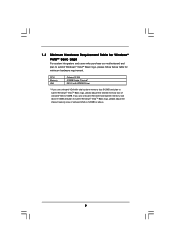
... to submit Windows® VistaTM Basic logo, please follow below table for Windows® VistaTM Basic Logo For system integrators and users who purchase our motherboard and plan to 64MB. CPU Memory VGA Celeron D 326 512MB Single Channel* DX9.0 with WDDM Driver * If you use onboard VGA with total system memory...
... to submit Windows® VistaTM Basic logo, please follow below table for Windows® VistaTM Basic Logo For system integrators and users who purchase our motherboard and plan to 64MB. CPU Memory VGA Celeron D 326 512MB Single Channel* DX9.0 with WDDM Driver * If you use onboard VGA with total system memory...

User Manual
Page 10
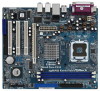
...) 26 Infrared Module Header (IR1) 13 Primary Serial ATA Connector (SATA1) 27 CPU Fan Connector (CPU_FAN1) 14 System Panel Header (PANEL1) 10 1.4 Motherboard Layout PS2 Keyboard 1 2 3 45 PS2 Mouse 1 PS2_USB_PWR1 ATX12V1 6 7 20.8cm (8.2 in) IDE2 PARALLEL PORT Conroe FSB1066 Quad Core CPU RAID... Chipset PCI EXPRESS IDE1 9 Super I/O 24 23 22 21 LAN PHY 4Mb BIOS Audio CODEC CD1 1 HD_AUDIO1 7.1 CH HD PCIE1 PCI1 4CoreDX90-VSTA PCI2 USB2.0 PCI3 HDMR1 USB4_5 1 USB6_7 1 VIA VT8237A FLOPPY1 CMOS Battery CLRCMOS1 SPEAKER1 1 PANEL 1 PLED PWRBTN 1 HDLED RESET SATA1 SATA2...
...) 26 Infrared Module Header (IR1) 13 Primary Serial ATA Connector (SATA1) 27 CPU Fan Connector (CPU_FAN1) 14 System Panel Header (PANEL1) 10 1.4 Motherboard Layout PS2 Keyboard 1 2 3 45 PS2 Mouse 1 PS2_USB_PWR1 ATX12V1 6 7 20.8cm (8.2 in) IDE2 PARALLEL PORT Conroe FSB1066 Quad Core CPU RAID... Chipset PCI EXPRESS IDE1 9 Super I/O 24 23 22 21 LAN PHY 4Mb BIOS Audio CODEC CD1 1 HD_AUDIO1 7.1 CH HD PCIE1 PCI1 4CoreDX90-VSTA PCI2 USB2.0 PCI3 HDMR1 USB4_5 1 USB6_7 1 VIA VT8237A FLOPPY1 CMOS Battery CLRCMOS1 SPEAKER1 1 PANEL 1 PLED PWRBTN 1 HDLED RESET SATA1 SATA2...

User Manual
Page 12
... the following precautions before installing or removing the motherboard. To avoid damaging the motherboard components due to the motherboard, peripherals, and/or components. 12 Chapter 2 Installation 4CoreDX90-VSTA is detached from the wall socket before you install motherboard components or change any component, place it . Before you uninstall any motherboard settings. 1. Unplug the power cord from the...
... the following precautions before installing or removing the motherboard. To avoid damaging the motherboard components due to the motherboard, peripherals, and/or components. 12 Chapter 2 Installation 4CoreDX90-VSTA is detached from the wall socket before you install motherboard components or change any component, place it . Before you uninstall any motherboard settings. 1. Unplug the power cord from the...

User Manual
Page 14
... socket: Step 4-1. Step 4-2. While pressing down lightly on center of PnP cap to assist in removal. 1. Step 3. This cap must be placed if returning the motherboard for after service. Step 4-3. For proper inserting, please ensure to match the two orientation key notches of the CPU with right hand thumb and peel...
... socket: Step 4-1. Step 4-2. While pressing down lightly on center of PnP cap to assist in removal. 1. Step 3. This cap must be placed if returning the motherboard for after service. Step 4-3. For proper inserting, please ensure to match the two orientation key notches of the CPU with right hand thumb and peel...

User Manual
Page 15
... type of heatsink and cooling fan compliant with remaining fasteners. 2.4 Installation of CPU Fan and Heatsink This motherboard is an example to the CPU fan connector on the motherboard (CPU_FAN1, see page 10, No. 4). Below is equipped with each other components. 15 Rotate the fastener... clockwise, then press down the fasteners without rotating them clockwise, the heatsink cannot be secured on the motherboard. Ensure that supports Intel 775-LAND CPU. Step 5. Place the heatsink onto the socket. Apply thermal interface material onto center ...
... type of heatsink and cooling fan compliant with remaining fasteners. 2.4 Installation of CPU Fan and Heatsink This motherboard is an example to the CPU fan connector on the motherboard (CPU_FAN1, see page 10, No. 4). Below is equipped with each other components. 15 Rotate the fastener... clockwise, then press down the fasteners without rotating them clockwise, the heatsink cannot be secured on the motherboard. Ensure that supports Intel 775-LAND CPU. Step 5. Place the heatsink onto the socket. Apply thermal interface material onto center ...

User Manual
Page 16
Please make sure to the motherboard and the DIMM if you force the DIMM into the slot until the retaining clips at incorrect orientation. notch break notch break The DIMM only ... both ends fully snap back in one correct orientation. Unlock a DIMM slot by pressing the retaining clips outward. Step 3. 2.5 Installation of Memory Modules (DIMM) This motherboard is properly seated. 16 Align a DIMM on the slot such that the notch on the DIMM matches the break on the slot. It will cause...
Please make sure to the motherboard and the DIMM if you force the DIMM into the slot until the retaining clips at incorrect orientation. notch break notch break The DIMM only ... both ends fully snap back in one correct orientation. Unlock a DIMM slot by pressing the retaining clips outward. Step 3. 2.5 Installation of Memory Modules (DIMM) This motherboard is properly seated. 16 Align a DIMM on the slot such that the notch on the DIMM matches the break on the slot. It will cause...

User Manual
Page 17
PCI slots: PCI slots are 3 PCI slots, 1 HDMR slot and 1 PCI Express slot on this motherboard. If you intend to use . Step 2. Step 3. Before installing the expansion card, please make necessary hardware settings for PCI Express cards with x16 lane width ...
PCI slots: PCI slots are 3 PCI slots, 1 HDMR slot and 1 PCI Express slot on this motherboard. If you intend to use . Step 2. Step 3. Before installing the expansion card, please make necessary hardware settings for PCI Express cards with x16 lane width ...

User Manual
Page 19
...will cause permanent damage of your hard disk drive to the primary IDE connector (IDE1, blue) and CD-ROM to the instruction of the motherboard! Please refer to the secondary IDE connector (IDE2, black). Placing jumper caps over these headers and connectors. Serial ATA Connectors (SATA1: see... p.10, No. 13) (SATA2: see p.10, No. 8) PIN1 IDE1 PIN1 IDE2 connect the blue end to the motherboard connect the black end to optimize compatibility and performance, please connect your IDE device vendor for internal storage devices. Serial ATA (SATA) Data Cable (...
...will cause permanent damage of your hard disk drive to the primary IDE connector (IDE1, blue) and CD-ROM to the instruction of the motherboard! Please refer to the secondary IDE connector (IDE2, black). Placing jumper caps over these headers and connectors. Serial ATA Connectors (SATA1: see... p.10, No. 13) (SATA2: see p.10, No. 8) PIN1 IDE1 PIN1 IDE2 connect the blue end to the motherboard connect the black end to optimize compatibility and performance, please connect your IDE device vendor for internal storage devices. Serial ATA (SATA) Data Cable (...

User Manual
Page 20
... connector allows you to the power connector of audio devices. 1. Then connect the white end of SATA power cable to the power connector on this motherboard. USB 2.0 Headers (9-pin USB6_7) (see p.10 No. 11) (9-pin USB4_5) (see p.10 No. 10) USB_PWR P-7 P+7 GND DUMMY 1 GND P+6 P-6 USB_PWR USB_PWR P-4 P+4 GND DUMMY 1 GND P+5 P-5 USB_PWR Besides...
... connector allows you to the power connector of audio devices. 1. Then connect the white end of SATA power cable to the power connector on this motherboard. USB 2.0 Headers (9-pin USB6_7) (see p.10 No. 11) (9-pin USB4_5) (see p.10 No. 10) USB_PWR P-7 P+7 GND DUMMY 1 GND P+6 P-6 USB_PWR USB_PWR P-4 P+4 GND DUMMY 1 GND P+5 P-5 USB_PWR Besides...

User Manual
Page 21
D. Enter Windows system. Though this connector and match the black wire to this motherboard provides 4-Pin CPU fan (Quiet Fan) support, the 3-Pin CPU fan still can work successfully even without the fan speed control function. Connect Audio_R (RIN...pin PANEL1) (see p.10, No. 14) Chassis Speaker Header (4-pin SPEAKER 1) (see p.10, No. 4) GND +12V CHA_FAN_SPEED Please connect the chassis fan cable to this motherboard, please connect it to OUT2_L. Set the Front Panel Control option from [Auto] to Ground (GND). Chassis Fan Connector (3-pin CHA_FAN1) (see p.10, No. 16...
D. Enter Windows system. Though this connector and match the black wire to this motherboard provides 4-Pin CPU fan (Quiet Fan) support, the 3-Pin CPU fan still can work successfully even without the fan speed control function. Connect Audio_R (RIN...pin PANEL1) (see p.10, No. 14) Chassis Speaker Header (4-pin SPEAKER 1) (see p.10, No. 4) GND +12V CHA_FAN_SPEED Please connect the chassis fan cable to this motherboard, please connect it to OUT2_L. Set the Front Panel Control option from [Auto] to Ground (GND). Chassis Fan Connector (3-pin CHA_FAN1) (see p.10, No. 16...

User Manual
Page 23
...the SATA hard disk. 2.10 Hot Plug and Hot Swap Functions for SATA HDDs 4CoreDX90-VSTA motherboard supports Hot Plug and Hot Swap functions for the action to insert and remove ...SATA hard disks. What is Hot Plug Function? 2.9 Serial ATA (SATA) Hard Disks Installation This motherboard adopts VIA® VT8237A southbridge chipset that it cannot perform Hot Plug if the OS has been installed...the SATA data cable to the SATA hard disk. STEP 2: Connect the SATA power cable to the motherboard's SATA connector. NOTE What is Hot Swap Function? If SATA HDDs are NOT set for RAID configuration,...
...the SATA hard disk. 2.10 Hot Plug and Hot Swap Functions for SATA HDDs 4CoreDX90-VSTA motherboard supports Hot Plug and Hot Swap functions for the action to insert and remove ...SATA hard disks. What is Hot Plug Function? 2.9 Serial ATA (SATA) Hard Disks Installation This motherboard adopts VIA® VT8237A southbridge chipset that it cannot perform Hot Plug if the OS has been installed...the SATA data cable to the SATA hard disk. STEP 2: Connect the SATA power cable to the motherboard's SATA connector. NOTE What is Hot Swap Function? If SATA HDDs are NOT set for RAID configuration,...

User Manual
Page 24
... conventional power connector interfaces, the IDE 1x4-pin conventional power connector interface is indicated in the product spec on our support website: www.asrock.com 4. SATA power cable with SATA 15-pin power connector interface A. SATA power cable SATA 7-pin connector The SATA 15-pin power...connect to SATA HDD 1x4-pin conventional power connector (White) connect to use the SATA power cable & data cable, which are from our motherboard package. 5. The SATA HDD, which cannot support Hot Plug function, will cause the HDD damage and data loss. Please read below instructions step...
... conventional power connector interfaces, the IDE 1x4-pin conventional power connector interface is indicated in the product spec on our support website: www.asrock.com 4. SATA power cable with SATA 15-pin power connector interface A. SATA power cable SATA 7-pin connector The SATA 15-pin power...connect to SATA HDD 1x4-pin conventional power connector (White) connect to use the SATA power cable & data cable, which are from our motherboard package. 5. The SATA HDD, which cannot support Hot Plug function, will cause the HDD damage and data loss. Please read below instructions step...

User Manual
Page 25
the motherboard's SATA connector. SATA power cable 1x4-pin power connector (White) Step 3 Connect SATA 15-pin power cable connector (Black) end to the power supply 1x4-...
the motherboard's SATA connector. SATA power cable 1x4-pin power connector (White) Step 3 Connect SATA 15-pin power cable connector (Black) end to the power supply 1x4-...

User Manual
Page 26
... follow the order from our support CD to your system now, but in the future, you plan to use HDMR card function on this motherboard. Please follow the steps below then. 1. Therefore, the drivers you finish installing all drivers to your system. 3. Install HDMR card driver from up to bottom ... Then, the drivers compatible to your system can work properly. 2.13 HDMR Card and Driver Installation If you do not insert HDMR card to this motherboard, and you install can be auto-detected and listed on the slot. 2.
... follow the order from our support CD to your system now, but in the future, you plan to use HDMR card function on this motherboard. Please follow the steps below then. 1. Therefore, the drivers you finish installing all drivers to your system. 3. Install HDMR card driver from up to bottom ... Then, the drivers compatible to your system can work properly. 2.13 HDMR Card and Driver Installation If you do not insert HDMR card to this motherboard, and you install can be auto-detected and listed on the slot. 2.
User Manual
Page 29
...® XP, Windows® XP 64-bit, Windows® VistaTM or Windows® VistaTM 64-bit OS on your system. 2.16 Untied Overclocking Technology This motherboard supports Untied Overclocking Technology, which will show you apply Untied Overclocking Technology. 29 If you want to [Auto], which means during overclocking, but PCI / PCIE...
...® XP, Windows® XP 64-bit, Windows® VistaTM or Windows® VistaTM 64-bit OS on your system. 2.16 Untied Overclocking Technology This motherboard supports Untied Overclocking Technology, which will show you apply Untied Overclocking Technology. 29 If you want to [Auto], which means during overclocking, but PCI / PCIE...

User Manual
Page 30
... the following BIOS setup screens and descriptions are for reference purpose only, and they may run the BIOS SETUP UTILITY when you see on the motherboard stores the BIOS SETUP UTILITY. Please press during the Power-On-Self-Test (POST) to configure your screen. 3.1.1 BIOS Menu Bar The top of the...
... the following BIOS setup screens and descriptions are for reference purpose only, and they may run the BIOS SETUP UTILITY when you see on the motherboard stores the BIOS SETUP UTILITY. Please press during the Power-On-Self-Test (POST) to configure your screen. 3.1.1 BIOS Menu Bar The top of the...

