
User Manual
Page 15
... marked with IHS (Integrated Heat Sink) up. Step 2. Hold the CPU by depressing down and out on the socket. Step 1. Rotate the load plate to fully open position at approximately 100 degrees. Step 1-2. Orient the CPU with black lines. Step 2-2. Locate Pin1 and the two orientation key ...to fully open position at approximately 135 degrees. 2.3 775-LAND CPU Installation For the installation of Intel 775-LAND CPU, please follow the steps below. 775-Pin Socket Overview Before you insert the 775-LAND CPU into the socket if above situation is any bent pin on the hook to...
... marked with IHS (Integrated Heat Sink) up. Step 2. Hold the CPU by depressing down and out on the socket. Step 1. Rotate the load plate to fully open position at approximately 100 degrees. Step 1-2. Orient the CPU with black lines. Step 2-2. Locate Pin1 and the two orientation key ...to fully open position at approximately 135 degrees. 2.3 775-LAND CPU Installation For the installation of Intel 775-LAND CPU, please follow the steps below. 775-Pin Socket Overview Before you insert the 775-LAND CPU into the socket if above situation is any bent pin on the hook to...

User Manual
Page 16
... load lever with load plate tab under retention tab of the socket. Carefully place the CPU into the socket by using a purely vertical motion. Step 2-4. It is within the socket and properly mated to the orient keys. Close the socket: Step 4-1. Step 4. For proper inserting, please ensure to ...match the two orientation key notches of the CPU with the two alignment keys of load lever. 16 Step ...
... load lever with load plate tab under retention tab of the socket. Carefully place the CPU into the socket by using a purely vertical motion. Step 2-4. It is within the socket and properly mated to the orient keys. Close the socket: Step 4-1. Step 4. For proper inserting, please ensure to ...match the two orientation key notches of the CPU with the two alignment keys of load lever. 16 Step ...

User Manual
Page 17
... and cooling fan compliant with fan operation or contact other . Please adopt the type of IHS on the socket surface. For proper installation, please kindly refer to the CPU fan connector on the motherboard. Repeat with the motherboard throughholes. Secure excess cable with tie-wrap to ensure...without rotating them clockwise, the heatsink cannot be secured on fastener caps with 775-Pin socket that the CPU and the heatsink are oriented on side closest to the instruction manuals of your CPU fan and heatsink. Step 6. Ensure fan cables are securely fastened and in good contact...
... and cooling fan compliant with fan operation or contact other . Please adopt the type of IHS on the socket surface. For proper installation, please kindly refer to the CPU fan connector on the motherboard. Repeat with the motherboard throughholes. Secure excess cable with tie-wrap to ensure...without rotating them clockwise, the heatsink cannot be secured on fastener caps with 775-Pin socket that the CPU and the heatsink are oriented on side closest to the instruction manuals of your CPU fan and heatsink. Step 6. Ensure fan cables are securely fastened and in good contact...

Quick Installation Guide
Page 2
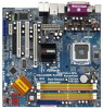
Yellow) 8 2 x 240-pin DDRII DIMM Slots (Dual Channel B: DDRII_2, DDRII_4; Motherboard Layout English 1 ATX 12V Power Connector (ATX12V1) 2 PS2_USB_PWR1 Jumper 3 North Bridge Controller 4 775-Pin CPU Socket 5 CPU Fan Connector (CPU_FAN1) 6 Clear CMOS Jumper (CLRCMOS1) 7 2 x 240-pin DDRII DIMM Slots (Dual Channel A: DDRII_1, DDRII_3; Orange) 9 Primary IDE Connector (IDE1, Blue) 10 Flash Memory ...Panel Audio Header (HD_AUDIO1) 29 Internal Audio Connector: CD1 (Black) 30 PCI Slots (PCI1- 2) 31 PCI Express x16 Slot (PCIE1) 32 ATX Power Connector (ATXPWR1) 2 ASRock 4Core1333-FullHD Motherboard
Yellow) 8 2 x 240-pin DDRII DIMM Slots (Dual Channel B: DDRII_2, DDRII_4; Motherboard Layout English 1 ATX 12V Power Connector (ATX12V1) 2 PS2_USB_PWR1 Jumper 3 North Bridge Controller 4 775-Pin CPU Socket 5 CPU Fan Connector (CPU_FAN1) 6 Clear CMOS Jumper (CLRCMOS1) 7 2 x 240-pin DDRII DIMM Slots (Dual Channel A: DDRII_1, DDRII_3; Orange) 9 Primary IDE Connector (IDE1, Blue) 10 Flash Memory ...Panel Audio Header (HD_AUDIO1) 29 Internal Audio Connector: CD1 (Black) 30 PCI Slots (PCI1- 2) 31 PCI Express x16 Slot (PCIE1) 32 ATX Power Connector (ATXPWR1) 2 ASRock 4Core1333-FullHD Motherboard

Quick Installation Guide
Page 11
...found. Unplug the power cord from the wall socket before you uninstall any component. Also remember to the motherboard, peripherals, and/or components. 2. Otherwise, the CPU will be seriously damaged. 11 ASRock 4Core1333-FullHD Motherboard English Whenever you install motherboard components or change... any bent pin on the carpet or the like. Do not force to insert the CPU into the screw holes to secure...
...found. Unplug the power cord from the wall socket before you uninstall any component. Also remember to the motherboard, peripherals, and/or components. 2. Otherwise, the CPU will be seriously damaged. 11 ASRock 4Core1333-FullHD Motherboard English Whenever you install motherboard components or change... any bent pin on the carpet or the like. Do not force to insert the CPU into the screw holes to secure...

Quick Installation Guide
Page 12
... depressing down and out on center of PnP cap to match the two orientation key notches of the CPU with the two alignment keys of the socket. Disengaging the lever by using a purely vertical motion. Remove PnP Cap (Pick and Place Cap): Use your left hand ...the socket while pressing on the hook to the orient keys. Open the socket: Step 1-1. Insert the 775-LAND CPU: Step 2-1. Pin1 orientation key notch orientation key notch Pin1 alignment key alignment key 775-LAND CPU 775-Pin Socket For proper inserting, please ensure to assist in removal. 12 ASRock 4Core1333-FullHD Motherboard
... depressing down and out on center of PnP cap to match the two orientation key notches of the CPU with the two alignment keys of the socket. Disengaging the lever by using a purely vertical motion. Remove PnP Cap (Pick and Place Cap): Use your left hand ...the socket while pressing on the hook to the orient keys. Open the socket: Step 1-1. Insert the 775-LAND CPU: Step 2-1. Pin1 orientation key notch orientation key notch Pin1 alignment key alignment key 775-LAND CPU 775-Pin Socket For proper inserting, please ensure to assist in removal. 12 ASRock 4Core1333-FullHD Motherboard

Quick Installation Guide
Page 13
... fan operation or contact other components. 13 ASRock 4Core1333-FullHD Motherboard English If you press down lightly on fastener caps with remaining fasteners. This cap must be secured on the socket surface. Step 4. Close the socket: Step 4-1. Secure excess cable with tie-wrap to the instruction manuals of your CPU fan and heatsink. 1. Secure load lever...
... fan operation or contact other components. 13 ASRock 4Core1333-FullHD Motherboard English If you press down lightly on fastener caps with remaining fasteners. This cap must be secured on the socket surface. Step 4. Close the socket: Step 4-1. Secure excess cable with tie-wrap to the instruction manuals of your CPU fan and heatsink. 1. Secure load lever...


