Getting Started Guide
Page 3
... GUIDE Conventions 5 Related Documentation 5 1 PRODUCT OVERVIEW Introduction 7 Switch 4800G 24-Port 8 Switch 4800G PWR 48-Port 11 Switch 4800G PWR 24-Port 13 Switch 4800G 24-Port SFP 17 Switch 4800G 48-Port 18 System Specifications of the Switch 4800G Series 22 Pluggable Modules 22 Optional Interface Modules 23 CX4 Cable 24 2 PREPARATING TO INSTALL THE SWITCH Safety Precautions 25 Installation Site 25 Installation...
... GUIDE Conventions 5 Related Documentation 5 1 PRODUCT OVERVIEW Introduction 7 Switch 4800G 24-Port 8 Switch 4800G PWR 48-Port 11 Switch 4800G PWR 24-Port 13 Switch 4800G 24-Port SFP 17 Switch 4800G 48-Port 18 System Specifications of the Switch 4800G Series 22 Pluggable Modules 22 Optional Interface Modules 23 CX4 Cable 24 2 PREPARATING TO INSTALL THE SWITCH Safety Precautions 25 Installation Site 25 Installation...
Getting Started Guide
Page 22
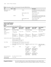
... high frequency. 22 CHAPTER 1: PRODUCT OVERVIEW Table 6 Description of LEDs on the front panel of the Switch 4800G Item Switch 4800G 24-Port Switch 4800G PWR 48-Port Switch 4800G PWR 24-Port Switch 4800G 24-Port SFP Switch 4800G 48-Port Physical dimensions (H × W × D) 43.6 × 440 × 300 mm... × 17.3 × 14.2 in the full duplex mode. The port fails the POST. System Specifications of the Switch 4800G Series Table 7 System specifications of the Switch 4800G 48-Port LED Mark Status SFP port status LED (100 Mbps) Speed Yellow Duplex Flashing yellow (3 Hz)...
... high frequency. 22 CHAPTER 1: PRODUCT OVERVIEW Table 6 Description of LEDs on the front panel of the Switch 4800G Item Switch 4800G 24-Port Switch 4800G PWR 48-Port Switch 4800G PWR 24-Port Switch 4800G 24-Port SFP Switch 4800G 48-Port Physical dimensions (H × W × D) 43.6 × 440 × 300 mm... × 17.3 × 14.2 in the full duplex mode. The port fails the POST. System Specifications of the Switch 4800G Series Table 7 System specifications of the Switch 4800G 48-Port LED Mark Status SFP port status LED (100 Mbps) Speed Yellow Duplex Flashing yellow (3 Hz)...
Getting Started Guide
Page 23
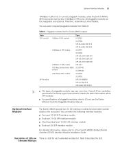
... GE SFP interface module For detailed information, please refer to 3Com Low End Series Ethernet Switches Pluggable Modules Manual. Consult 3Com marketing personnel or technical support personnel to obtain the latest information about SFP modules. ■ For specifications of pluggable modules, refer to 3Com Switch 4800G Family Ethernet Switches GE/10G Interface Module Installation Guide. You can select...
... GE SFP interface module For detailed information, please refer to 3Com Low End Series Ethernet Switches Pluggable Modules Manual. Consult 3Com marketing personnel or technical support personnel to obtain the latest information about SFP modules. ■ For specifications of pluggable modules, refer to 3Com Switch 4800G Family Ethernet Switches GE/10G Interface Module Installation Guide. You can select...
Getting Started Guide
Page 26
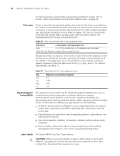
... output wires). To eliminate the interferences, pay attention to the following table lists the dust concentration limit. Laser Safety The Switch 4800G are rigorous limits on the content of harmful substances in the air that can accelerate the corrosion and aging of metals, such...but also cause communications failures. 26 CHAPTER 2: PREPARATING TO INSTALL THE SWITCH For the temperature and humidity requirements of different models, refer to section "System Specifications of the Switch 4800G Series" on the Switch 4800G is operating, do not stare into the optical port because the laser...
... output wires). To eliminate the interferences, pay attention to the following table lists the dust concentration limit. Laser Safety The Switch 4800G are rigorous limits on the content of harmful substances in the air that can accelerate the corrosion and aging of metals, such...but also cause communications failures. 26 CHAPTER 2: PREPARATING TO INSTALL THE SWITCH For the temperature and humidity requirements of different models, refer to section "System Specifications of the Switch 4800G Series" on the Switch 4800G is operating, do not stare into the optical port because the laser...

Getting Started Guide
Page 54
... new connection in the connection description interface and click OK. 54 CHAPTER 4: INITIAL POWER-ON 5 Parity: None 6 Stop bits: 1 7 Flow control: None 8 Emulation: VT100 The specific procedure is as shown below. Select the serial port to establish a new connection. The connection description interface appears, as follows: 1 Select Start > Programs > Accessories > Communications...
... new connection in the connection description interface and click OK. 54 CHAPTER 4: INITIAL POWER-ON 5 Parity: None 6 Stop bits: 1 7 Flow control: None 8 Emulation: VT100 The specific procedure is as shown below. Select the serial port to establish a new connection. The connection description interface appears, as follows: 1 Select Start > Programs > Accessories > Communications...
Getting Started Guide
Page 77
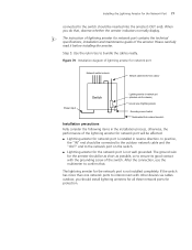
...In practice, the "IN" end should be connected to the outdoor network cable and the "OUT" end to the network port on the switch. ■ Lightning arrester for protection. Figure 70 Installation diagram of lightning arrester for network port Network cable indoors Network cable led into from...arresters for all these network ports for the network port is not installed completely. The ground wire for network port contains the technical specifications, installation and maintenance guide of lightning arrester for the arrester should be as short as possible, so to ensure its good contact with...
...In practice, the "IN" end should be connected to the outdoor network cable and the "OUT" end to the network port on the switch. ■ Lightning arrester for protection. Figure 70 Installation diagram of lightning arrester for network port Network cable indoors Network cable led into from...arresters for all these network ports for the network port is not installed completely. The ground wire for network port contains the technical specifications, installation and maintenance guide of lightning arrester for the arrester should be as short as possible, so to ensure its good contact with...