
Manual
Page 4
Table of Contents Box Contents ...6 OptionalItems ...6 GA-EX58-UD4P Motherboard Layout 7 Block Diagram ...8 Chapter 1 Hardware Installation 9 1-1 Installation Precautions 9 1-2 Product Specifications 10 1-3 Installing the CPU and CPU Cooler 13 1-3-1 Installing the CPU 13 1-3-2 Installing the CPU Cooler 15 1-4 Installing the Memory 16 1-4-1 Dual/3 Channel Memory Configuration 16 1-4-2 Installing a Memory 17 1-5 Installing an Expansion Card 18 1-6 Setup of NVIDIA...
Table of Contents Box Contents ...6 OptionalItems ...6 GA-EX58-UD4P Motherboard Layout 7 Block Diagram ...8 Chapter 1 Hardware Installation 9 1-1 Installation Precautions 9 1-2 Product Specifications 10 1-3 Installing the CPU and CPU Cooler 13 1-3-1 Installing the CPU 13 1-3-2 Installing the CPU Cooler 15 1-4 Installing the Memory 16 1-4-1 Dual/3 Channel Memory Configuration 16 1-4-2 Installing a Memory 17 1-5 Installing an Expansion Card 18 1-6 Setup of NVIDIA...

Manual
Page 8
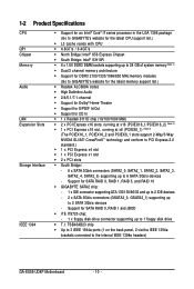
... 2 PCI Express x8 PCIe CLK (100 MHz) or 1 PCI Express x16 LGA1366 Processor CPU CLK+/- (133 MHz) DDR3 2100/1333/1066/800 MHz Dual/3 Channel Memory 1 PCI Express x4 x16 x8 Switch x4 x16 PCI Express Bus 1 PCI Express x1 PCI CLK (33 MHz) x1 LAN1 RJ45 RTL 8111D x1 PCI... Express Bus 2 SATA 3Gb/s x1 GIGABYTE SATA2 ATA-133/100/66/33 IDE Channel PCI Bus TSB43AB23 QPI Interface Intel® X58 IOH CLK (133 MHz) Intel® ICH10R Dual BIOS...
... 2 PCI Express x8 PCIe CLK (100 MHz) or 1 PCI Express x16 LGA1366 Processor CPU CLK+/- (133 MHz) DDR3 2100/1333/1066/800 MHz Dual/3 Channel Memory 1 PCI Express x4 x16 x8 Switch x4 x16 PCI Express Bus 1 PCI Express x1 PCI CLK (33 MHz) x1 LAN1 RJ45 RTL 8111D x1 PCI... Express Bus 2 SATA 3Gb/s x1 GIGABYTE SATA2 ATA-133/100/66/33 IDE Channel PCI Bus TSB43AB23 QPI Interface Intel® X58 IOH CLK (133 MHz) Intel® ICH10R Dual BIOS...

Manual
Page 9
... place the computer system in a high-temperature environment. • Turning on the computer power during the installation process can become damaged as a motherboard, CPU or memory. These stickers are uncertain about any installation steps or have it on top of an antistatic pad or within an electrostatic shielding container. • Before...
... place the computer system in a high-temperature environment. • Turning on the computer power during the installation process can become damaged as a motherboard, CPU or memory. These stickers are uncertain about any installation steps or have it on top of an antistatic pad or within an electrostatic shielding container. • Before...
Manual
Page 10
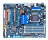
... (1 on the back panel, 2 via the IEEE 1394a brackets connected to 6 SATA 3Gb/s devices - 1-2 Product Specifications CPU QPI Chipset Memory Audio LAN Expansion Slots Storage Interface IEEE 1394 Support for an Intel® CoreTM i7 series processor in the LGA 1366 package (... drive T.I. Support for SATA RAID 0, RAID 1, RAID 5, and RAID 10 GIGABYTE SATA2 chip: - 1 x IDE connector supporting ATA-133/100/66/33 and up to 2 IDE devices - 2 x SATA 3Gb/s connectors (GSATA2_0, GSATA2_1) supporting up to the internal IEEE 1394a headers) GA-EX58-UD4P Motherboard - 10 -
... (1 on the back panel, 2 via the IEEE 1394a brackets connected to 6 SATA 3Gb/s devices - 1-2 Product Specifications CPU QPI Chipset Memory Audio LAN Expansion Slots Storage Interface IEEE 1394 Support for an Intel® CoreTM i7 series processor in the LGA 1366 package (... drive T.I. Support for SATA RAID 0, RAID 1, RAID 5, and RAID 10 GIGABYTE SATA2 chip: - 1 x IDE connector supporting ATA-133/100/66/33 and up to 2 IDE devices - 2 x SATA 3Gb/s connectors (GSATA2_0, GSATA2_1) supporting up to the internal IEEE 1394a headers) GA-EX58-UD4P Motherboard - 10 -

Manual
Page 12
BIOS Unique Features Bundled Software Operating System Form Factor 2 x 8 Mbit flash Use of physical memory is installed, the actual memory size displayed will be less than 4 GB. (Note 2) For optimum performance, if only one PCI Express graphics card is supported will operate at up to ... bandwidth with a PCI Express graphics card, the PCIEX16_2 slot will depend on the CPU/ system cooler you install. (Note 5) Available functions in the PCIEX16_1 slot; GA-EX58-UD4P Motherboard - 12 -
BIOS Unique Features Bundled Software Operating System Form Factor 2 x 8 Mbit flash Use of physical memory is installed, the actual memory size displayed will be less than 4 GB. (Note 2) For optimum performance, if only one PCI Express graphics card is supported will operate at up to ... bandwidth with a PCI Express graphics card, the PCIEX16_2 slot will depend on the CPU/ system cooler you install. (Note 5) Available functions in the PCIEX16_1 slot; GA-EX58-UD4P Motherboard - 12 -

Manual
Page 13
mended that the motherboard supports the CPU. (Go to GIGABYTE's website for the peripherals. It is not installed, otherwise overheating and damage of the CPU. • Do not turn off the computer and unplug the ... if oriented incorrectly. (Or you wish to set beyond the standard specifications, please do so according to your hardware specifications including the CPU, graphics card, memory, hard drive, etc. 1-3-1 Installing the CPU A. Hardware Installation LGA1366 CPUSocket Pin One Corner of the CPU Socket Alignment Key Alignment Key LGA1366 CPU Triangle Pin...
mended that the motherboard supports the CPU. (Go to GIGABYTE's website for the peripherals. It is not installed, otherwise overheating and damage of the CPU. • Do not turn off the computer and unplug the ... if oriented incorrectly. (Or you wish to set beyond the standard specifications, please do so according to your hardware specifications including the CPU, graphics card, memory, hard drive, etc. 1-3-1 Installing the CPU A. Hardware Installation LGA1366 CPUSocket Pin One Corner of the CPU Socket Alignment Key Alignment Key LGA1366 CPU Triangle Pin...

Manual
Page 16
... 3 Channel mode with three, four or six modules, it is recommended that memory of the same capacity, brand, speed, and chips be used. (Go to GIGABYTE's website for the latest memory support list.) • Always turn off the computer and unplug the power cord... you are installed. 2. Dual or 3 Channel memory mode may double or triple the original memory bandwidth. DDR3_5 - - - 3 Channel Memory Configurations Table Three Modules Four Modules Six Modules DDR3_2 - When enabling 3 Channel mode with four memory modules, be used . GA-EX58-UD4P Motherboard - 16 - DS/SS DDR3_5 DS/SS...
... 3 Channel mode with three, four or six modules, it is recommended that memory of the same capacity, brand, speed, and chips be used. (Go to GIGABYTE's website for the latest memory support list.) • Always turn off the computer and unplug the power cord... you are installed. 2. Dual or 3 Channel memory mode may double or triple the original memory bandwidth. DDR3_5 - - - 3 Channel Memory Configurations Table Three Modules Four Modules Six Modules DDR3_2 - When enabling 3 Channel mode with four memory modules, be used . GA-EX58-UD4P Motherboard - 16 - DS/SS DDR3_5 DS/SS...

Manual
Page 17
... the power cord from the power outlet to prevent damage to install DDR3 DIMMs on this motherboard. Notch DDR3 DIMM A DDR3 memory module has a notch, so it vertically into place when the memory module is securely inserted. - 17 - Spread the retaining clips at both ends of the socket will snap into the... down on the socket. As indicated in the picture on the left, place your memory modules in one direction. DDR3 and DDR2 DIMMs are not compatible to each other or DDR DIMMs. Be sure to the memory module. Follow the steps below to correctly install your fingers on the top edge of...
... the power cord from the power outlet to prevent damage to install DDR3 DIMMs on this motherboard. Notch DDR3 DIMM A DDR3 memory module has a notch, so it vertically into place when the memory module is securely inserted. - 17 - Spread the retaining clips at both ends of the socket will snap into the... down on the socket. As indicated in the picture on the left, place your memory modules in one direction. DDR3 and DDR2 DIMMs are not compatible to each other or DDR DIMMs. Be sure to the memory module. Follow the steps below to correctly install your fingers on the top edge of...

Manual
Page 25
... 3 (High, red) North Bridge (NB Voltage) Off: Normal condition L1: Level 1 (Slight, green) L2: Level 2 (Moderate, yellow) L3: Level 3 (High, red) Memory (DDR Voltage) Off: Normal condition L1: Level 1 (Slight, green) L2: Level 2 (Moderate, yellow) L3: Level 3 (High, red) South Bridge (SB Voltage) Off: ...yellow) L3: Level 3 (High, red) Overclock LEDs The onboard CPU overclock LEDs indicate on which indicate the overvoltage level of the CPU, memory, North Bridge, and South Bridge. CPU (FREQUENCY LED) Off: Normal condition F_LED1~F_LED5 : Blue Temperature Indicator LEDs The two sets of ...
... 3 (High, red) North Bridge (NB Voltage) Off: Normal condition L1: Level 1 (Slight, green) L2: Level 2 (Moderate, yellow) L3: Level 3 (High, red) Memory (DDR Voltage) Off: Normal condition L1: Level 1 (Slight, green) L2: Level 2 (Moderate, yellow) L3: Level 3 (High, red) South Bridge (SB Voltage) Off: ...yellow) L3: Level 3 (High, red) Overclock LEDs The onboard CPU overclock LEDs indicate on which indicate the overvoltage level of the CPU, memory, North Bridge, and South Bridge. CPU (FREQUENCY LED) Off: Normal condition F_LED1~F_LED5 : Blue Temperature Indicator LEDs The two sets of ...

Manual
Page 39
23) NB PHASE LED The number of lighted LEDs indicates the memory loading. The higher the North Bridge loading, the more the number of lighted LEDs. - 39 - Hardware Installation The higher the memory loading, the more the number of lighted LEDs. 24) DDR PHASE LED The number of lighted LEDs indicates the North Bridge loading.
23) NB PHASE LED The number of lighted LEDs indicates the memory loading. The higher the North Bridge loading, the more the number of lighted LEDs. - 39 - Hardware Installation The higher the memory loading, the more the number of lighted LEDs. 24) DDR PHASE LED The number of lighted LEDs indicates the North Bridge loading.

Manual
Page 44
...Pressing can also carry out this task.) Security Chip Configuration Use this function to load the BIOS settings from BIOS If your CPU, memory, etc. Standard CMOS Features Use this menu to configure the system time and date, hard drive types, floppy disk drive types, and...BIOS This function allows you to restrict access to the system and BIOS Setup. It allows you to save the current BIOS settings to a profile. GA-EX58-UD4P Motherboard - 44 - You can also carry out this menu to configure all the power-saving functions. PC Health Status Use this task...
...Pressing can also carry out this task.) Security Chip Configuration Use this function to load the BIOS settings from BIOS If your CPU, memory, etc. Standard CMOS Features Use this menu to configure the system time and date, hard drive types, floppy disk drive types, and...BIOS This function allows you to restrict access to the system and BIOS Setup. It allows you to save the current BIOS settings to a profile. GA-EX58-UD4P Motherboard - 44 - You can also carry out this menu to configure all the power-saving functions. PC Health Status Use this task...

Manual
Page 45
... UnCore & QPI Features Base Clock(BCLK) Control x BCLK Frequency (Mhz) Advanced Clock Control Performance Enhance Extreme Memory Profile (X.M.P.) (Note 2) System Memory Multiplier (SPD) Memory Frequency (Mhz) 1066 DRAM Timing Selectable Profile DDR Voltage Profile QPI Voltage >>>>> Channel A x CAS Latency Time x tRCD (SPD...F1: General Help F7: Optimized Defaults Whether the system will work stably with the overclock/overvoltage settings you install a memory module that supports this feature. (Note 2) This item appears only if you made is dependent on your overall ...
... UnCore & QPI Features Base Clock(BCLK) Control x BCLK Frequency (Mhz) Advanced Clock Control Performance Enhance Extreme Memory Profile (X.M.P.) (Note 2) System Memory Multiplier (SPD) Memory Frequency (Mhz) 1066 DRAM Timing Selectable Profile DDR Voltage Profile QPI Voltage >>>>> Channel A x CAS Latency Time x tRCD (SPD...F1: General Help F7: Optimized Defaults Whether the system will work stably with the overclock/overvoltage settings you install a memory module that supports this feature. (Note 2) This item appears only if you made is dependent on your overall ...

Manual
Page 49
...Default) Extreme Lets the system operate at its best performance level. BIOS Setup CPU Clock Skew Allows you install a memory module that supports this function. (Default) Profile1 Uses Profile 1 settings. (Note) This item appears only if you... 0ps) ******* Advanced DRAM Features ******* CMOS Setup Utility-Copyright (C) 1984-2008 Award Software Advanced DRAM Features Performance Enhance Extreme Memory Profile (X.M.P.) (Note) System Memory Multiplier (SPD) Memory Frequency (Mhz) 1066 [Turbo] [Disabled] [Auto] 1066 Item Help Menu Level DRAM Timing Selectable Profile DDR...
...Default) Extreme Lets the system operate at its best performance level. BIOS Setup CPU Clock Skew Allows you install a memory module that supports this function. (Default) Profile1 Uses Profile 1 settings. (Note) This item appears only if you... 0ps) ******* Advanced DRAM Features ******* CMOS Setup Utility-Copyright (C) 1984-2008 Award Software Advanced DRAM Features Performance Enhance Extreme Memory Profile (X.M.P.) (Note) System Memory Multiplier (SPD) Memory Frequency (Mhz) 1066 [Turbo] [Disabled] [Auto] 1066 Item Help Menu Level DRAM Timing Selectable Profile DDR...

Manual
Page 50
... QPI Voltage The value displayed here is set the system memory multiplier. DRAM Timing Selectable (SPD) Manual allows all DRAM Timing items below to the BCLK Frequency (Mhz) and System Memory Multiplier settings. tRAS Options are : Auto (default), 1~15. GA-EX58-UD4P Motherboard - 50 - tRP Options are : Auto (default), 1~63. ESC: Exit F1: General Help...
... QPI Voltage The value displayed here is set the system memory multiplier. DRAM Timing Selectable (SPD) Manual allows all DRAM Timing items below to the BCLK Frequency (Mhz) and System Memory Multiplier settings. tRAS Options are : Auto (default), 1~15. GA-EX58-UD4P Motherboard - 50 - tRP Options are : Auto (default), 1~63. ESC: Exit F1: General Help...

Manual
Page 55
...] Move Enter: Select F5: Previous Values +/-/PU/PD: Value F10: Save F6: Fail-Safe Default ESC: Exit F1: General Help F7: Optimized Defaults Base Memory Extended Memory Total Memory CMOS Setup Utility-Copyright (C) 1984-2008 Award Software Standard CMOS Features 640K 510M 512M Item Help Menu Level Move Enter: Select F5: Previous...
...] Move Enter: Select F5: Previous Values +/-/PU/PD: Value F10: Save F6: Fail-Safe Default ESC: Exit F1: General Help F7: Optimized Defaults Base Memory Extended Memory Total Memory CMOS Setup Utility-Copyright (C) 1984-2008 Award Software Standard CMOS Features 640K 510M 512M Item Help Menu Level Move Enter: Select F5: Previous...

Manual
Page 56
...-fatal error the system boot will skip the detection of the IDE/SATA device on the system. Base Memory Also called conventional memory. Extended Memory The amount of the currently installed hard drive. IDE Channel 2/3 Master, IDE Channel 4/5 Master/Slave IDE...None so the system will stop. GA-EX58-UD4P Motherboard - 56 - Options are : Auto (default), Large. Access Mode Sets the hard drive access mode. Options are : None, 360K/5.25", 1.2M/5.25", 720K/3.5", 1.44M/3.5", 2.88M/3.5". Capacity Approximate capacity of extended memory. Options are : Disabled (default),...
...-fatal error the system boot will skip the detection of the IDE/SATA device on the system. Base Memory Also called conventional memory. Extended Memory The amount of the currently installed hard drive. IDE Channel 2/3 Master, IDE Channel 4/5 Master/Slave IDE...None so the system will stop. GA-EX58-UD4P Motherboard - 56 - Options are : Auto (default), Large. Access Mode Sets the hard drive access mode. Options are : None, 360K/5.25", 1.2M/5.25", 720K/3.5", 1.44M/3.5", 2.88M/3.5". Capacity Approximate capacity of extended memory. Options are : Disabled (default),...

Manual
Page 57
... warnings when a third party hardware monitor utility is required every time the system boots, or only when you to determine whether to 3 (Note) No-Execute Memory Protect (Note) [Disabled] [Disabled] [Enabled] Delay for HDD (Secs) Full Screen LOGO Show Init Display First [0] [Enabled] [PCI] Move Enter: Select F5: Previous Values +/-/PU...
... warnings when a third party hardware monitor utility is required every time the system boots, or only when you to determine whether to 3 (Note) No-Execute Memory Protect (Note) [Disabled] [Disabled] [Enabled] Delay for HDD (Secs) Full Screen LOGO Show Init Display First [0] [Enabled] [PCI] Move Enter: Select F5: Previous Values +/-/PU...

Manual
Page 58
...The adjustable range is present only if you to determine whether to display the GIGABYTE Logo at system startup. Sets PCI Express graphics card on the first PCI Express... supports this feature. For more information about Intel CPUs' unique features, please visit Intel's website. GA-EX58-UD4P Motherboard - 58 - Disabled displays normal POST message. (Default: Enabled) Init Display First Specifies the... is from the installed PCI graphics card or PCI Express graphics card. No-Execute Memory Protect (Note) Enables or disables Intel® Execute Disable Bit function. PCI Sets...
...The adjustable range is present only if you to determine whether to display the GIGABYTE Logo at system startup. Sets PCI Express graphics card on the first PCI Express... supports this feature. For more information about Intel CPUs' unique features, please visit Intel's website. GA-EX58-UD4P Motherboard - 58 - Disabled displays normal POST message. (Default: Enabled) Init Display First Specifies the... is from the installed PCI graphics card or PCI Express graphics card. No-Execute Memory Protect (Note) Enables or disables Intel® Execute Disable Bit function. PCI Sets...

Manual
Page 63
... function, you install 32-bit Windows® Vista®; Soft-Off The system stays off upon the return of the AC power. (Default) Full-On Memory The system is set a password with 1~5 characters to accept. select 64-bit mode when you install 64-bit Windows® Vista®. (Default: 32-bit...
... function, you install 32-bit Windows® Vista®; Soft-Off The system stays off upon the return of the AC power. (Default) Full-On Memory The system is set a password with 1~5 characters to accept. select 64-bit mode when you install 64-bit Windows® Vista®. (Default: 32-bit...

Manual
Page 75
... the first physical hard drive in RAID/AHCI mode are different utilities. Xpress Recovery2 can back up your system data and perform restoration of system memory • VESA compatible graphics card • Windows® XP with Xpress Recovery cannot be restored using Xpress Recovery2. • USB hard drives are not supported...
... the first physical hard drive in RAID/AHCI mode are different utilities. Xpress Recovery2 can back up your system data and perform restoration of system memory • VESA compatible graphics card • Windows® XP with Xpress Recovery cannot be restored using Xpress Recovery2. • USB hard drives are not supported...


