
Manual
Page 4
... Expansion Card 18 1-6 Setup of NVIDIA SLI (Scalable Link Interface)/ATI CrossFireX Configuration ... 19 1-7 Installing the SATA Bracket 22 1-8 Back Panel Connectors 23 1-9 Onboard LEDs and Switches 25 1-10 Internal Connectors 27 Chapter 2 BIOS Setup 41 2-1 Startup Screen 42 2-2 The Main Menu 43 2-3 MB Intelligent Tweaker(M.I.T 45 2-4 Standard CMOS Features 55 2-5 Advanced BIOS Features 57 2-6 IntegratedPeripherals 59 2-7 Power Management Setup 62 2-8 PC Health Status 64 2-9 Load Fail-Safe Defaults 66 2-10 Load Optimized Defaults 66 2-11 Set Supervisor/User Password...
... Expansion Card 18 1-6 Setup of NVIDIA SLI (Scalable Link Interface)/ATI CrossFireX Configuration ... 19 1-7 Installing the SATA Bracket 22 1-8 Back Panel Connectors 23 1-9 Onboard LEDs and Switches 25 1-10 Internal Connectors 27 Chapter 2 BIOS Setup 41 2-1 Startup Screen 42 2-2 The Main Menu 43 2-3 MB Intelligent Tweaker(M.I.T 45 2-4 Standard CMOS Features 55 2-5 Advanced BIOS Features 57 2-6 IntegratedPeripherals 59 2-7 Power Management Setup 62 2-8 PC Health Status 64 2-9 Load Fail-Safe Defaults 66 2-10 Load Optimized Defaults 66 2-11 Set Supervisor/User Password...
Manual
Page 10
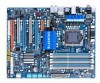
... 3 IEEE 1394a ports (1 on the back panel, 2 via the IEEE 1394a brackets connected to the internal IEEE 1394a headers) GA-EX58-UD4P Motherboard - 10 - Support for SATA RAID 0, RAID 1 and JBOD iTE IT8720 chip: - 1 x floppy disk drive connector supporting up to 6 SATA 3Gb/s devices - 1-2 Product Specifications CPU QPI Chipset Memory Audio LAN Expansion Slots Storage Interface IEEE 1394 Support for an Intel® CoreTM i7 series processor in the LGA 1366 package (Go to GIGABYTE's website for the latest CPU support list.) L3...
... 3 IEEE 1394a ports (1 on the back panel, 2 via the IEEE 1394a brackets connected to the internal IEEE 1394a headers) GA-EX58-UD4P Motherboard - 10 - Support for SATA RAID 0, RAID 1 and JBOD iTE IT8720 chip: - 1 x floppy disk drive connector supporting up to 6 SATA 3Gb/s devices - 1-2 Product Specifications CPU QPI Chipset Memory Audio LAN Expansion Slots Storage Interface IEEE 1394 Support for an Intel® CoreTM i7 series processor in the LGA 1366 package (Go to GIGABYTE's website for the latest CPU support list.) L3...

Manual
Page 16
... the POST. DS/SS DDR3_1 DS/SS DS/SS DDR3_4 - When enabling Dual Channel mode with two or four modules, it is installed, be sure to prevent hardware damage. • Memory modules have a foolproof design. Intel® Flex Memory Technology offers greater flexibility to upgrade by allowing different memory sizes to be sure to install them in the DDR3_1 and DDR3_3 sockets. 3 Channel-1. 3 Channel mode cannot be used...
... the POST. DS/SS DDR3_1 DS/SS DS/SS DDR3_4 - When enabling Dual Channel mode with two or four modules, it is installed, be sure to prevent hardware damage. • Memory modules have a foolproof design. Intel® Flex Memory Technology offers greater flexibility to upgrade by allowing different memory sizes to be sure to install them in the DDR3_1 and DDR3_3 sockets. 3 Channel-1. 3 Channel mode cannot be used...

Manual
Page 29
When connecting a fan cable, be sure to connect it in the correct orientation. The motherboard supports CPU fan speed control, which requires the use of a CPU fan with color-coded power connector wires. Definition 1 GND 2 +12V / Speed Control 3 Sense 4 Speed Control SYS_FAN2: Pin No. When connecting a fan cable, be installed inside the chassis. 1 CPU_FAN 1 SYS_FAN2 1 SYS_FAN3 1 SYS_FAN1/ PWR_FAN CPU_FAN: Pin No. Definition 1 GND 2 +12V 3 NC • Be sure to connect fan cables to the fan headers to the CPU/North Bridge or the system may...
When connecting a fan cable, be sure to connect it in the correct orientation. The motherboard supports CPU fan speed control, which requires the use of a CPU fan with color-coded power connector wires. Definition 1 GND 2 +12V / Speed Control 3 Sense 4 Speed Control SYS_FAN2: Pin No. When connecting a fan cable, be installed inside the chassis. 1 CPU_FAN 1 SYS_FAN2 1 SYS_FAN3 1 SYS_FAN1/ PWR_FAN CPU_FAN: Pin No. Definition 1 GND 2 +12V 3 NC • Be sure to connect fan cables to the fan headers to the CPU/North Bridge or the system may...

Manual
Page 44
..., hard drive types, floppy disk drive types, and the type of errors that stop the system boot, etc. Advanced BIOS Features Use this menu to configure the device boot order, advanced features available on the CPU, and the primary display adapter. Integrated Peripherals Use this menu to configure all peripheral devices, such as IDE, SATA, USB, integrated audio, and integrated LAN, etc. Power Management Setup Use this menu to see information about autodetected system/CPU temperature, system voltage and fan speed, etc. Load...
..., hard drive types, floppy disk drive types, and the type of errors that stop the system boot, etc. Advanced BIOS Features Use this menu to configure the device boot order, advanced features available on the CPU, and the primary display adapter. Integrated Peripherals Use this menu to configure all peripheral devices, such as IDE, SATA, USB, integrated audio, and integrated LAN, etc. Power Management Setup Use this menu to see information about autodetected system/CPU temperature, system voltage and fan speed, etc. Load...

Manual
Page 47
... Speed Uncore Frequency Uncore Frequency Isochronous Support CMOS Setup Utility-Copyright (C) 1984-2008 Award Software UnCore & QPI Features [Auto] 4.8GHz [Auto] 2667MHz [Enabled] Item Help Menu Level Move Enter: Select F5: Previous Values +/-/PU/PD: Value F10: Save F6: Fail-Safe Defaults ESC: Exit F1: General Help F7: Optimized Defaults QPI Link Speed Allows you to decrease average power consumption and heat production. (Default: Enabled) Virtualization Technology (Note) Enables or disables Intel® Virtualization Technology. Options are : Auto (default...
... Speed Uncore Frequency Uncore Frequency Isochronous Support CMOS Setup Utility-Copyright (C) 1984-2008 Award Software UnCore & QPI Features [Auto] 4.8GHz [Auto] 2667MHz [Enabled] Item Help Menu Level Move Enter: Select F5: Previous Values +/-/PU/PD: Value F10: Save F6: Fail-Safe Defaults ESC: Exit F1: General Help F7: Optimized Defaults QPI Link Speed Allows you to decrease average power consumption and heat production. (Default: Enabled) Virtualization Technology (Note) Enables or disables Intel® Virtualization Technology. Options are : Auto (default...

Manual
Page 48
... CPU computing power to be set the PCIe clock frequency. Racing Increases CPU frequency by 17% or 19% depending on CPU loading through the use of C.I .A.2) is from 90 MHz to manually set in accordance with the CPU specifications. GA-EX58-UD4P Motherboard - 48 - Turbo Increases CPU frequency by 7% or 9% depending on CPU loading. This item is configurable only if the Base Clock(BCLK) Control option is highly recommended that the CPU frequency be configurable. Disabled Disables the use of 5 preset states. Sports Increases CPU frequency...
... CPU computing power to be set the PCIe clock frequency. Racing Increases CPU frequency by 17% or 19% depending on CPU loading through the use of C.I .A.2) is from 90 MHz to manually set in accordance with the CPU specifications. GA-EX58-UD4P Motherboard - 48 - Turbo Increases CPU frequency by 7% or 9% depending on CPU loading. This item is configurable only if the Base Clock(BCLK) Control option is highly recommended that the CPU frequency be configurable. Disabled Disables the use of 5 preset states. Sports Increases CPU frequency...

Manual
Page 53
... the CPU voltage more constant under light and heavy CPU load. QPI/Vtt Voltage The default is Auto. ******* Advanced Voltage Control ******* CMOS Setup Utility-Copyright (C) 1984-2008 Award Software Advanced Voltage Control Voltage Types Normal Current >>> CPU Load-Line Calibration [Disabled] CPU Vcore 1.12500V [Auto] QPI/Vtt Voltage 1.200V [Auto] CPU PLL 1.800V [Auto] >>> MCH/ICH PCIE 1.500V [Auto] QPI PLL 1.100V [Auto] IOH Core 1.100V [Auto ICH I/O 1.500V [Auto] ICH Core 1.100V [Auto] >>> DRAM DRAM Voltage 1.500V [Auto] DRAM Termination 0.750V [Auto] Ch...
... the CPU voltage more constant under light and heavy CPU load. QPI/Vtt Voltage The default is Auto. ******* Advanced Voltage Control ******* CMOS Setup Utility-Copyright (C) 1984-2008 Award Software Advanced Voltage Control Voltage Types Normal Current >>> CPU Load-Line Calibration [Disabled] CPU Vcore 1.12500V [Auto] QPI/Vtt Voltage 1.200V [Auto] CPU PLL 1.800V [Auto] >>> MCH/ICH PCIE 1.500V [Auto] QPI PLL 1.100V [Auto] IOH Core 1.100V [Auto ICH I/O 1.500V [Auto] ICH Core 1.100V [Auto] >>> DRAM DRAM Voltage 1.500V [Auto] DRAM Termination 0.750V [Auto] Ch...

Manual
Page 57
... list. set the password(s) under the Set Supervisor/User Password item in the BIOS Main Menu. BIOS Setup Options are: Floppy, LS120, Hard Disk, CDROM, ZIP, USB-FDD, USB-ZIP, USB-CDROM, USB-HDD, Legacy LAN, Disabled. to Disabled for Windows XP operating system; First/Second/Third Boot Device Specifies the boot order from the installed hard drives. Setup System A password is only required for HDD (Secs) Full Screen LOGO Show Init Display First [0] [Enabled] [PCI] Move Enter: Select F5: Previous Values +/-/PU/PD: Value F10: Save F6: Fail-Safe Defaults...
... list. set the password(s) under the Set Supervisor/User Password item in the BIOS Main Menu. BIOS Setup Options are: Floppy, LS120, Hard Disk, CDROM, ZIP, USB-FDD, USB-ZIP, USB-CDROM, USB-HDD, Legacy LAN, Disabled. to Disabled for Windows XP operating system; First/Second/Third Boot Device Specifies the boot order from the installed hard drives. Setup System A password is only required for HDD (Secs) Full Screen LOGO Show Init Display First [0] [Enabled] [PCI] Move Enter: Select F5: Previous Values +/-/PU/PD: Value F10: Save F6: Fail-Safe Defaults...

Manual
Page 58
.... No-Execute Memory Protect (Note) Enables or disables Intel® Execute Disable Bit function. Disabled displays normal POST message. (Default: Enabled) Init Display First Specifies the first initiation of the monitor display from 0 to initialize the hard drive as the first display. Sets PCI Express graphics card on the second PCI Express x16 slot (PCIEX16_2) as the system boots up. The adjustable range is present only if you to determine whether to display the GIGABYTE Logo at...
.... No-Execute Memory Protect (Note) Enables or disables Intel® Execute Disable Bit function. Disabled displays normal POST message. (Default: Enabled) Init Display First Specifies the first initiation of the monitor display from 0 to initialize the hard drive as the first display. Sets PCI Express graphics card on the second PCI Express x16 slot (PCIEX16_2) as the system boots up. The adjustable range is present only if you to determine whether to display the GIGABYTE Logo at...

Manual
Page 59
... to be used in MS-DOS. (Default: Disabled) USB Mouse Function Allows USB mouse to operate in Legacy IDE mode. 2-6 Integrated Peripherals CMOS Setup Utility-Copyright (C) 1984-2008 Award Software Integrated Peripherals SATA RAID/AHCI Mode SATA Port0-3 Native Mode USB 1.0 Controller USB 2.0 Controller USB Keyboard Function USB Mouse Function USB Storage Function Azalia Codec Onboard H/W 1394 Onboard H/W LAN Green LAN SMART LAN Onboard LAN Boot ROM Onboard SATA/IDE Device Onboard SATA/IDE Ctrl Mode [Disabled] [Disabled] [Enabled] [Enabled] [Disabled] [Disabled] [Enabled] [Auto...
... to be used in MS-DOS. (Default: Disabled) USB Mouse Function Allows USB mouse to operate in Legacy IDE mode. 2-6 Integrated Peripherals CMOS Setup Utility-Copyright (C) 1984-2008 Award Software Integrated Peripherals SATA RAID/AHCI Mode SATA Port0-3 Native Mode USB 1.0 Controller USB 2.0 Controller USB Keyboard Function USB Mouse Function USB Storage Function Azalia Codec Onboard H/W 1394 Onboard H/W LAN Green LAN SMART LAN Onboard LAN Boot ROM Onboard SATA/IDE Device Onboard SATA/IDE Ctrl Mode [Disabled] [Disabled] [Enabled] [Enabled] [Disabled] [Disabled] [Enabled] [Auto...

Manual
Page 60
... using the onboard LAN, set this item to Disabled. Link Detected --> 100Mbps Cable Length= 30m GA-EX58-UD4P Motherboard - 60 - Onboard H/W 1394 Enables or disables the onboard IEEE 1394 function. (Default: Enabled) Onboard H/W LAN Enables or disables the onboard LAN function. (Default: Enabled) If you wish to install a 3rd party add-in audio card instead of wires will detect cabling issue and report the approximate distance to the fault or short. USB Storage Function Determines whether to detect USB storage devices, including USB flash drives and USB hard drives during...
... using the onboard LAN, set this item to Disabled. Link Detected --> 100Mbps Cable Length= 30m GA-EX58-UD4P Motherboard - 60 - Onboard H/W 1394 Enables or disables the onboard IEEE 1394 function. (Default: Enabled) Onboard H/W LAN Enables or disables the onboard LAN function. (Default: Enabled) If you wish to install a 3rd party add-in audio card instead of wires will detect cabling issue and report the approximate distance to the fault or short. USB Storage Function Determines whether to detect USB storage devices, including USB flash drives and USB hard drives during...

Manual
Page 61
... in Windows mode or when the LAN Boot ROM is an interface specification that allows the storage driver to AHCI mode. When a Cable Problem Occurs... Onboard LAN Boot ROM Allows you to decide whether to activate the boot ROM integrated with the onboard LAN chip. (Default: Disabled) Onboard SATA/IDE Device (GIGABYTE SATA2 Chip) Enables or disables the IDE and SATA controllers integrated in the GIGABYTE SATA2 chip. (Default: Enabled) Onboard SATA/IDE Ctrl Mode (GIGABYTE SATA2 Chip) Enables or disables RAID for the SATA controller integrated in PATA mode) - 61 - IDE Disables RAID for...
... in Windows mode or when the LAN Boot ROM is an interface specification that allows the storage driver to AHCI mode. When a Cable Problem Occurs... Onboard LAN Boot ROM Allows you to decide whether to activate the boot ROM integrated with the onboard LAN chip. (Default: Disabled) Onboard SATA/IDE Device (GIGABYTE SATA2 Chip) Enables or disables the IDE and SATA controllers integrated in the GIGABYTE SATA2 chip. (Default: Enabled) Onboard SATA/IDE Ctrl Mode (GIGABYTE SATA2 Chip) Enables or disables RAID for the SATA controller integrated in PATA mode) - 61 - IDE Disables RAID for...

Manual
Page 65
... 4-pin CPU fan. PWM Sets PWM mode for a 4-pin CPU fan that is set for a 3-pin CPU fan. BIOS Setup CPU Smart FAN Control Enables or disables the CPU fan speed control function. This item is configurable only if CPU Smart FAN Control is not designed following Intel PWM fan specifications, selecting PWM mode may not effectively reduce the fan speed. - 65 - You can be set to Enabled. Auto Lets BIOS autodetect the type of CPU fan installed and sets the optimal CPU fan control mode. (Default) Voltage Sets Voltage mode for a 3-pin CPU fan or a 4-pin CPU fan. Note: The Voltage mode...
... 4-pin CPU fan. PWM Sets PWM mode for a 4-pin CPU fan that is set for a 3-pin CPU fan. BIOS Setup CPU Smart FAN Control Enables or disables the CPU fan speed control function. This item is configurable only if CPU Smart FAN Control is not designed following Intel PWM fan specifications, selecting PWM mode may not effectively reduce the fan speed. - 65 - You can be set to Enabled. Auto Lets BIOS autodetect the type of CPU fan installed and sets the optimal CPU fan control mode. (Default) Voltage Sets Voltage mode for a 3-pin CPU fan or a 4-pin CPU fan. Note: The Voltage mode...

Manual
Page 79
... key during the POST to update BIOS?" Q-Flash Utility v2.08 Flash Type/Size SST 25VF080B 1M Enter : Run Keep DMI Data Enable !! Step 1: 1. appears, press to select Update BIOS from Drive Sa0vefilBeI(Os)SfotounDdrive :Move ESC:Reset :Power Off Total size : 0 Free size : 0 3. Unique Features CoUpypdBaItOe SBIcOomS pfrloetmedD-rPivaess !! Insert the floppy disk containing the BIOS file into the floppy disk drive. Make sure the BIOS update file matches your motherboard model. Select the BIOS update file and press . The monitor will display...
... key during the POST to update BIOS?" Q-Flash Utility v2.08 Flash Type/Size SST 25VF080B 1M Enter : Run Keep DMI Data Enable !! Step 1: 1. appears, press to select Update BIOS from Drive Sa0vefilBeI(Os)SfotounDdrive :Move ESC:Reset :Power Off Total size : 0 Free size : 0 3. Unique Features CoUpypdBaItOe SBIcOomS pfrloetmedD-rPivaess !! Insert the floppy disk containing the BIOS file into the floppy disk drive. Make sure the BIOS update file matches your motherboard model. Select the BIOS update file and press . The monitor will display...
Manual
Page 82
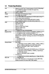
... in EasyTune 6 may differ by motherboard model. GA-EX58-UD4P Motherboard - 82 - The Memory tab provides information on the installed CPU and motherboard. The Tuner tab allows you to adjust system clock settings and voltages. • Quick Boost mode provides you set temperature/fan speed alarm. After making changes in Easy mode/Advanced mode, be sure to default values, be changed linearly based on a specific slot to monitor hardware temperature, voltage and fan speed and set . The EasyTune 6 Interface Tabs Information...
... in EasyTune 6 may differ by motherboard model. GA-EX58-UD4P Motherboard - 82 - The Memory tab provides information on the installed CPU and motherboard. The Tuner tab allows you to adjust system clock settings and voltages. • Quick Boost mode provides you set temperature/fan speed alarm. After making changes in Easy mode/Advanced mode, be sure to default values, be changed linearly based on a specific slot to monitor hardware temperature, voltage and fan speed and set . The EasyTune 6 Interface Tabs Information...

Manual
Page 95
... of the SATA hard drive and the other end to available SATA port on your power supply to enter BIOS Setup during the POST. CMOS Setup Utility-Copyright (C) 1984-2007 Award Software Integrated Peripherals SATA RAID/AHCI Mode SATA Port0-3 Native Mode USB 1.0 Controller USB 2.0 Controller USB Keyboard Function USB Mouse Function USB Storage Function Azalia Codec Onboard H/W 1394 Onboard H/W LAN Green LAN SMART LAN Onboard LAN Boot ROM Onboard SATA/IDE Device Onboard SATA/IDE Ctrl Mode [Disabled] [Disabled] [Enabled] [Enabled] [Disabled] [Disabled] [Enabled] [Auto] [Enabled] [Enabled...
... of the SATA hard drive and the other end to available SATA port on your power supply to enter BIOS Setup during the POST. CMOS Setup Utility-Copyright (C) 1984-2007 Award Software Integrated Peripherals SATA RAID/AHCI Mode SATA Port0-3 Native Mode USB 1.0 Controller USB 2.0 Controller USB Keyboard Function USB Mouse Function USB Storage Function Azalia Codec Onboard H/W 1394 Onboard H/W LAN Green LAN SMART LAN Onboard LAN Boot ROM Onboard SATA/IDE Device Onboard SATA/IDE Ctrl Mode [Disabled] [Disabled] [Enabled] [Enabled] [Disabled] [Disabled] [Enabled] [Auto] [Enabled] [Enabled...
Manual
Page 96
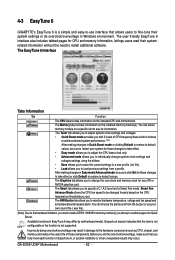
... Main Menu ] [ Hard Disk Drive List ] Create RAID Disk Drive Delete RAID Disk Drive Revert HDD to Non-RAID Solve Mirror Conflict Rebuild Mirror Drive Save And Exit Setup Exit Without Saving Model Name HDD0: ST3120026AS HDD1: ST3120026AS Capacity 120 GB 120 GB Type/Status Non-RAID Non-RAID [ RAID Disk Drive List ] [TAB]-Switch Window []-Select ITEM [ENTER]-Action Figure 3 [ESC]-Exit Note: In the main screen, you wish to configure a RAID array. Press + to enter RAID Setup Utility ... GA-EX58-UD4P Motherboard - 96 - GIGABYTE Technology...
... Main Menu ] [ Hard Disk Drive List ] Create RAID Disk Drive Delete RAID Disk Drive Revert HDD to Non-RAID Solve Mirror Conflict Rebuild Mirror Drive Save And Exit Setup Exit Without Saving Model Name HDD0: ST3120026AS HDD1: ST3120026AS Capacity 120 GB 120 GB Type/Status Non-RAID Non-RAID [ RAID Disk Drive List ] [TAB]-Switch Window []-Select ITEM [ENTER]-Action Figure 3 [ESC]-Exit Note: In the main screen, you wish to configure a RAID array. Press + to enter RAID Setup Utility ... GA-EX58-UD4P Motherboard - 96 - GIGABYTE Technology...

Manual
Page 103
... chosen to configure a SCSI Adapter for use with the Windows XP installation. - 103 - For GIGABYTE SATA2 SATA controller: Insert the floppy disk containing the SATA RAID/AHCI driver and press . After the driver installation, you want from the following list, or press ESC to return to the previous screen. (Windows XP/2003) RAID/AHCI Driver for GIGABYTE GBB36X Controller (Windows 2000) RAID Driver for GIGABYTE GBB363 Controller (Windows 2000) AHCI Driver for GIGABYTE GBB363 Controller (Windows 2000) RAID Driver for GIGABYTE GBB36X Controller and press . Then a controller menu similar to...
... chosen to configure a SCSI Adapter for use with the Windows XP installation. - 103 - For GIGABYTE SATA2 SATA controller: Insert the floppy disk containing the SATA RAID/AHCI driver and press . After the driver installation, you want from the following list, or press ESC to return to the previous screen. (Windows XP/2003) RAID/AHCI Driver for GIGABYTE GBB36X Controller (Windows 2000) RAID Driver for GIGABYTE GBB363 Controller (Windows 2000) AHCI Driver for GIGABYTE GBB363 Controller (Windows 2000) RAID Driver for GIGABYTE GBB36X Controller and press . Then a controller menu similar to...

Manual
Page 120
... with power/ amplifier. Turn off your computer. Q: Why do I still get a weak sound even though I clear the CMOS values? A: The following Award BIOS beep code descriptions may help you identify possible computer problems. (For reference only.) 1 short: System boots successfully 2 short: CMOS setting error 1 long, 1 short: Memory or motherboard error 1 long, 2 short: Monitor or graphics card error 1 long, 3 short: Keyboard error 1 long, 9 short: BIOS ROM error Continuous long beeps: Graphics card not inserted properly Continuous short beeps: Power error GA-EX58-UD4P Motherboard - 120...
... with power/ amplifier. Turn off your computer. Q: Why do I still get a weak sound even though I clear the CMOS values? A: The following Award BIOS beep code descriptions may help you identify possible computer problems. (For reference only.) 1 short: System boots successfully 2 short: CMOS setting error 1 long, 1 short: Memory or motherboard error 1 long, 2 short: Monitor or graphics card error 1 long, 3 short: Keyboard error 1 long, 9 short: BIOS ROM error Continuous long beeps: Graphics card not inserted properly Continuous short beeps: Power error GA-EX58-UD4P Motherboard - 120...


