eMachines D732Z Support Question
eMachines D732Z Support Question
Find answers below for this question about eMachines D732Z.Need a eMachines D732Z manual? We have 1 online manual for this item!
Question posted by warren453 on November 8th, 2013
Ram Support
I was about to upgrade its RAM, but I'm not sure what is its max memory support per DIMM module.. if its 2gb, 4gb or 8gb..
Current Answers
Answer #1: Posted by BusterDoogen on November 8th, 2013 5:16 PM
BusterDoogen

Member since:
October 30th, 2011 Points: 28,565,447

Member since:
October 30th, 2011 Points: 28,565,447
Up to 2 GB of dual-channel DDR3 667 MHz memory, upgradeable to 8 GB using two 4GB soDIMM modules.
I hope this is helpful to you!
Please respond to my effort to provide you with the best possible solution by using the "Acceptable Solution" and/or the "Helpful" buttons when the answer has proven to be helpful. Please feel free to submit further info for your question, if a solution was not provided. I appreciate the opportunity to serve you!
Related eMachines D732Z Manual Pages
User Guide - Page 5

Screw Type
Chapter 3
57
Remove the one (1) screw securing the ODD module in place. Step
ODD Module Disassembly
Size M2.5*6.5
Quantity 1
3.
Grasp the ODD by the bezel and slide it out of the chassis. See "Removing the Battery Pack" on page 53. 2. Removing the ODD Module
1.
User Guide - Page 7

Main Unit Disassembly Process
Main Unit Disassembly Flowchart
NOTE: Use the process highlighted in red to access the Bluetooth module
Screw List Step
Lower Cover Battery Bay WLAN Module Disassembly USB Module Disassembly HDD Module
Screw M2.5*6.5 M2.0*3.0 M2.0*3.0 M2.5*4.0 M2-0.4*2
Quantity 17 6 1 1 1
Part No. 86.ARE07.001 86.ARE07.002 86.ARE07.002 86.ARE07.002 86.W4107.002
Chapter 3
59
User Guide - Page 8

... Process" on page 52. 2. Step HDD Carrier Disassembly LCD Module Disassembly Thermal Module Disassembly Mainboard Disassembly
Screw M3.0*3.5 M2.5*6.5 M2.5*4.0 M2.5*4.0
Quantity 4 4 1 1
Removing the Lower Cover
1.
Part No. 86.N1407.007 86.ARE07.001 86.R6Z07.001 86....
User Guide - Page 10

Disassembly Overview
1. This section is an overview of the major components of the main unit.
1
23
9
8
Item 1 2 3 4 5
Description RTC battery LVDS cable Thermal module WLAN module DIMM module(s)
76 5
4
Item 6 7 8 9
Description CPU Bluetooth cable HDD USB module
62
Chapter 3 See "Removing the Lower Cover" on page 60. 2.
User Guide - Page 11
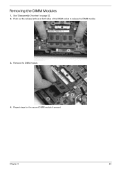
Remove the DIMM module.
4. Repeat steps for the second DIMM module if present. Removing the DIMM Modules
1. See "Disassembly Overview" on both sides of the DIMM socket to release the DIMM module.
3.
Chapter 3
63 Push out the release latches on page 62. 2.
User Guide - Page 12
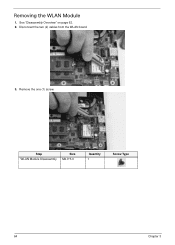
See "Disassembly Overview" on page 62. 2. Disconnect the two (2) cables from the WLAN board.
3. Step WLAN Module Disassembly
Size M2.0*3.0
Quantity 1
Screw Type
64
Chapter 3 Remove the one (1) screw.
Removing the WLAN Module
1.
User Guide - Page 14
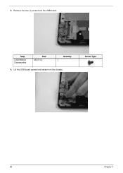
Lift the USB board upward and away from the USB board. Screw Type
66
Chapter 3 3. Step
USB Module Disassembly
Size M2.5*4.0
Quantity 1
4.
Remove the one (1) screw from the chassis.
User Guide - Page 16

Removing the HDD Module
1. Using the pull-tab, slide the HDD module in the direction of the arrow to the mainboard. Remove the one (1) screw securing the HDD module to disconnect the interface.
68
Chapter 3
See "Disassembly Overview" on page 62. 2. Step HDD Module
Size M2-0.4*2
Quantity 1
Screw Type
3.
User Guide - Page 18
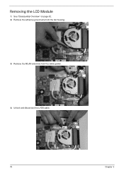
Remove the WLAN antennas from the fan housing.
3. Unlock and disconnect the LVDS cable.
70
Chapter 3 Removing the LCD Module
1. Remove the adhesive ground wire from the cable guides.
4. See "Disassembly Overview" on page 62. 2.
User Guide - Page 19
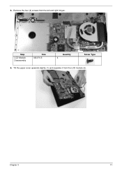
Tilt the upper cover upwards slightly (1) and separate it from the left and right hinges. Step
LCD Module Disassembly
Size M2.5*6.5
Quantity 4
Screw Type
6.
5. Remove the four (4) screws from the LCD module (2).
2
1
Chapter 3
71
User Guide - Page 20
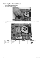
Disconnect the fan cable as shown.
3. See "Disassembly Overview" on page 62. 2. Loosen the four (4) captive screws (in numerical order from 1 to 4) and remove the one (1) screw from the fan module.
4
1
3
Step
Thermal Module Disassembly
Size
M2.5*4.0 (green callout)
2
Quantity 1
Screw Type
72
Chapter 3 Removing the Thermal Module
1.
User Guide - Page 21
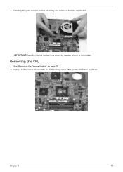
Removing the CPU
1. Using a slotted screw driver, rotate the CPU locking screw 180° counter-clockwise as shown. IMPORTANT:Place the thermal module on page 72. 2.
4. Chapter 3
73 Carefully lift up the thermal module assembly and remove it is not installed. See "Removing the Thermal Module" on a clean, dry surface when it from the mainboard.
User Guide - Page 24
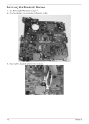
Disconnect the Bluetooth cable from the mainboard.
76
Chapter 3 Turn the mainboard over and locate the Bluetooth module.
3. See "Removing the Mainboard" on page 74. 2. Removing the Bluetooth Module
1.
User Guide - Page 25

Remove the mylar holder to expose the Bluetooth cable connector. Lift the Bluetooth module away from the mainboard. 5. 4. Chapter 3
77
User Guide - Page 26
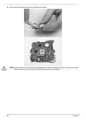
NOTE: Circuit boards >10 cm² have been highlighted with a yellow rectangle as shown in the previous image. Please detach the Circuit board and follow local regulations for disposal.
78
Chapter 3 Disconnect the Bluetooth cable from the Bluetooth module. 6.
User Guide - Page 28
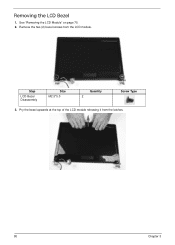
Removing the LCD Bezel
1. Step
LCD Bezel Disassembly
Size M2.5*5.0
Quantity 2
Screw Type
3. Remove the two (2) bezel screws from the latches.
80
Chapter 3
See "Removing the LCD Module" on page 70. 2. Pry the bezel upwards at the top of the LCD module releasing it from the LCD module.
User Guide - Page 29

Continue separating the latches along the sides of the LCD bezel. 6. Chapter 3
81 Release the latches at the bottom of the bezel towards the hinges. 5. Lift the bezel clear of the LCD module. 4.
User Guide - Page 30

NOTE: Take care not to damage the cable.
82
Chapter 3 Removing the Camera (CCD) Module
1. See "Removing the LCD Bezel" on page 80. 2. Disconnect the cable as shown. Lift the CCD module from the LCD cover.
3.
User Guide - Page 35

Place the black and white WLAN antennas into the cable guides as shown. LCD Module Assembly Process
Replacing the WLAN Antennas
1. Repeat for the white antenna.
2.
Place the black antenna cable onto the LCD cover as shown. Chapter 3
87
User Guide - Page 36

... that the cable is provided to secure the LVDS cable.
3. Turn the LCD panel face down on the panel to prevent damage to the CCD module.
Similar Questions

Sorry To Ask This, You Said It Is Upgradeable To 8gb Using 2x4gb Ddr3 667mhz..
but this site told me that only up to 4gb with with 2 soDIMM modules (2x2gb).. http://villman.com/Pr...
but this site told me that only up to 4gb with with 2 soDIMM modules (2x2gb).. http://villman.com/Pr...
(Posted by warren453 10 years ago)

Not Able To Install Driver In Windows 8
Hi I have an emachine D732z, i wanted to installed windows 8 in my system .i also have a emachine d...
Hi I have an emachine D732z, i wanted to installed windows 8 in my system .i also have a emachine d...
(Posted by jaydipparekh17 10 years ago)

My Acer Emachine Can Upgrade Ram?
Dear Sir, I have Acer emachine D725 wich contain 1 GB ram. Can I upgrade it till 4 GB or Above?
Dear Sir, I have Acer emachine D725 wich contain 1 GB ram. Can I upgrade it till 4 GB or Above?
(Posted by jaydevbudhbhatti 11 years ago)

Upgrading Cpu's
i found a d2244 emachine computer in a car at a local junkyard. it looked in excellent condition so ...
i found a d2244 emachine computer in a car at a local junkyard. it looked in excellent condition so ...
(Posted by mikehunts2big 12 years ago)