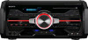
Sony HCD-SH2000 Support Question
Sony HCD-SH2000 Support Question
Find answers below for this question about Sony HCD-SH2000.Need a Sony HCD-SH2000 manual? We have 1 online manual for this item!
Question posted by mbmombeshora on October 13th, 2016
Power Supply Problem
My Sony HCD-SH2000 radio goes to standby and when you turn it 'ON', it switches 'OFF' completely after a few seconds. What could be the problem?
Current Answers
Answer #1: Posted by techyagent on October 13th, 2016 6:40 AM
techyagent

Member since:
June 17th, 2014 Points: 4,799,790

Member since:
June 17th, 2014 Points: 4,799,790
The problem is seems like the internal capacitors are faulty and you need to check this guide below.
Here i found something
How to repair a switching power supply like those used in DVD players, satellite receivers, VCRs ect. They are all very similar in design, if you can fix one, you can fix em all. Learn from a retired expert in the field.
You can check the link
Thanks
Techygirl
Related Sony HCD-SH2000 Manual Pages
Service Manual - Page 1
... × 235 mm × 420 mm Mass (excl. HCD-SH2000
SERVICE MANUAL
E Model
Ver. 1.1 2011.09
• HCD-SH2000 is the tuner, USB, CD and amplifier section in FST-SH2000/LBT-SH2000.
• "WALKMAN" and "WALKMAN" logo are registered trademarks of Sony Corporation. • MPEG Layer-3 audio coding technology and patents licensed from the objective lens...
Service Manual - Page 2
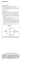
..." indication is 0.75 V, so analog meters must not exceed 0.5 mA (500 microamperes). A. COMPONENTS IDENTIFIED BY MARK 0 OR DOTTED LINE WITH MARK 0 ON THE SCHEMATIC DIAGRAMS AND IN THE ...REPLACE THESE COMPONENTS WITH SONY PARTS WHOSE PART NUMBERS APPEAR AS SHOWN IN THIS MANUAL OR IN SUPPLEMENTS PUBLISHED BY SONY.
2 HCD-SH2000
SAFETY CHECK-OUT After correcting the original service problem, perform...
Service Manual - Page 3
HCD-SH2000
TABLE OF ... Diagram - BUTTON, USB Board 47 5-33. AUDIO-IN Board 51 5-37. AUDIO-IN Board 51 5-38. Back Panel Section 7 2-3. SWITCHING REGULATOR 10
3. MAIN Section 16 5-3. Block Diagram... Diagram - CDM Section 69
7. TEST MODE 11
4. PANEL, POWER SUPPLY Section - . 18 5-5. MAIN Board (Component Side) (Suffix 12 22 5-8. Schematic Diagram - DMB21 Board...
Service Manual - Page 4
...capacitor may be added to ordinary solder. HCD-SH2000
Ver. 1.1
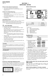
SECTION 1 SERVICING NOTES
Notes on chip component replacement • Never reuse a disconnected chip component. • Notice that the minus ... printed matter which compresses audio data. PART No.
UNLEADED SOLDER Boards requiring use the procedure in expansion format), or Multi Session 3)
1) MP3 (MPEG 1 Audio Layer 3) is a ...
Service Manual - Page 5
... HCD-SH2000
5
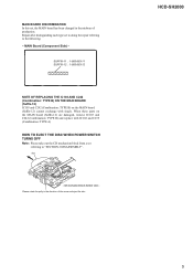
Please rotate the pully in the midway of the arrow and eject the disc. disc
- Repair after distinguishing each type set
referring to the following. - MAIN Board (Component Side...) - When these parts on the MAIN board (Suffix-12) cannot exchange with IC102 and C239 (Combination: TYPE A)
HOW TO EJECT THE DISC WHEN POWER SWITCH TURNS OFF Note...
Service Manual - Page 17
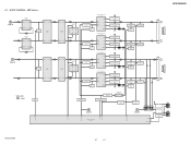
...+ OUTPUT 7
SIGNAL PATH
: AUDIO
MUTE Q207
51
/LINE-MUTE DAMP-CLK /DAMP-RESET
NO USE /SD-SLOW RESONANCE
D1403 D1435
HCD-SH2000
LOW SPEAKER IMPEDANCE USE 4ȍ
2 INA- BLOCK DIAGRAM - AMP Section - AOUT 1
PREAMP IC1404
5 INB+ BOUT 7
BUFFER IC1411
5
7
3
1
INA+ INB+ AOUT BOUT
INA+ INB+ AOUT BOUT
CEC DATA SWITCH Q1412
SWITCH Q1414
AMPLIFIER CONTROLLER...
Service Manual - Page 18

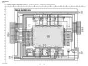
...HCD-SH2000
AVDD +5V DVDD +5V
RF +3.3V
+3.3V REGULATOR
IC107
TU +3.3V VBUS +5V
LED +13.5V LED +13.5V
TD FL TUBE
M +9V VM +9V
D +9V
+5V REGULATOR
IC804
+3.3V REGULATOR
IC1601
SWITCHING DRIVER Q803
DC-DC CONVERTER TRANSFOMER T900
SWITCHING Q906, Q907
SWITCHING Q804
SWITCHING...D1256 - PANEL, POWER SUPPLY Section - D1259 (DJ LED) D1280
(LED BAR2)
D1290 (LED BAR1)
D1251 (STANDBY LED)
LED ...
Service Manual - Page 19

...
Note on Printed Wiring Board:
• X : parts extracted from the component side.
•
: parts extracted from the conductor side.
•
:...panel designation. Line. • Voltage and waveforms are dc with a oscilloscope. F : AUDIO E : USB f : TUNER J : AUDIO (DIGITAL)
• Abbreviation E2 : 120 V AC area in μF unless otherwise ...HCD-SH2000
19
19
HCD-SH2000
Ver. 1.1
Service Manual - Page 20

...
"6%*0 */
-
3
D
%7%4"5
"6%*0 */
-3
E
- F
-&%
41&",&3
3
G
H
I
F700
3
1
3
1
J500
MAIN BOARD
(Component side)
DMB21
I BOARD CN4604 (Page 32)
DMB21
F BOARD CN602 (Page 32)
(CHASSIS)
DMB21
E BOARD CN1108 (Page 32)
DMB21
D BOARD...45)
AUDIO-IN
H BOARD NO1200 (Page 51)
11 (11)
CN704
CN705
(CHASSIS)
G
DAMP BOARD CN1400 (Page 37)
B
DAMP BOARD CN1401 (Page 37)
J
HCD-SH2000
20...
Service Manual - Page 22

...AUDIO-IN
H BOARD NO1200 (Page 51)
12 (12)
(CHASSIS)
G
DAMP BOARD CN1400 (Page 37)
B
DAMP BOARD CN1401 (Page 37)
J
HCD-SH2000
Note 1: Refer to the servicing notes "MAIN BOARD DISCRIMINATION" (page 5) for Circuit Boards Location. • : Uses unleaded solder.
1
2
3
4
5
6
7
8
9
10
11
12
13
14
15
A
MAIN BOARD (Component...1
R161
2 1
R158
CN100
14
1-883-863- HCD-SH2000
5-7.
Service Manual - Page 24
...0 JL150 50
0
AUDIO-CLK 49
JL149
0 48
JL148
0 AUDIO-DATA 47
JL147
0 FLASH-MEMORY 46
JL146
HUB-VBUS-DET 45 3.2 JL145
3.2
HUB-RESET 44
MTK-POWER-CTL 43 3.2 JL143... 0.1
C128 0.1
POWER SWITCHING Q204
RT1N141C-TP-1
0
3.1
0
9
11
10
R258
R259
4.7k
10k
14
13.4
12.7
LED SWITCH
Q205
2SB1690TL
13.4
MAIN
3 BOARD (3/4) (Page 26)
12
58
13
HCD-SH2000
24
24 SCHEMATIC DIAGRAM...
Service Manual - Page 27

...100 16V
G
13.5
30
R819 10k
R820 4.7k 0
MAIN
7 BOARD
(3/4)
31
(Page 26)
32
POWER SWITCH Q801
RT1N141C-TP-1 3.1
JL800
TV IN-L PC IN-L MIC REFOUT
PC IN-R TV IN-R
C548
C651...0.47
WHT J500
DVD/SAT
AUDIO IN
RED
L
R
33k 0.1
OUTPUT VCC INPUT- MAIN BOARD (4/4) (Suffix 11) - • See page 54 for IC Block Diagrams.
1
2
3
4
5
6
7
8
HCD-SH2000
9
10
11
12
13
14...
Service Manual - Page 56

HCD-SH2000
IC4601 PCM1808PWR (DMB21 BOARD (1/3))
BCK 8 SDO 9 MOD0 10 MOD1 11 FMT 12
Serial Interface Mode/ Format Control
x1/64 Decimation
Filter with High Pass Filter
Clock and Timing Control
7 LRCK 6 SCKI
AIN_L 13 IN_R 14
Delta Sigma Modulator
Delta Sigma Modulator
Antialias LPF
Reference
Antialias LPF
Power Supply
5 DGND 4 DVDD 3 AVCC 2 AGND
1 VREF
56
Service Manual - Page 57

... 1 DATA 2 LRCK 3
DGND 4 NC 5
VCC (5V) 6
POWER SUPPLY
AUDIO SERIAL PORT
SERIAL CONTROL
PORT
4x/8x OVERSAMPLING DIGITAL FILTER & FUNCTION CONTROL
...AUDIO INPUT PORT
RATE ESTIMATOR
AUDIO OUTPUT
PORT
BYPAS 9 IFMT0 10 IFMT1 11 IFMT2 12
RST 13 MUTE 14
CONTROL LOGIC
28 MODE2 27 MODE1 26 MODE0
25 BCKO 24 LRCKO 23 SDOUT
22 VDD 21 DGND
20 TDMI
19 OFMT0 18 OFMT1 17 OWL0 16 OWL1 15 RDY
HCD-SH2000...
Service Manual - Page 61

...audio signal processor, R2A15216FP
50
NO-USE
O Unused
51
/LINE-MUTE
O Muting Control Switch for several hundreds msec and then change to LED Driver, R8A66166SP
BYTE
- Ground terminal
15
XIN
I Main system clock input terminal (8MHz)
16
VCC
- Power supply... "L": reset I After the power supply rises, "L" is input for all speaker mute control pin. HCD-SH2000
• IC Pin Function ...
Service Manual - Page 62
... switch CDM open close switch CDM motor revious CDM motor forward Standby LED Destination setting terminal (A/D input) Unused MTK DMB Board power monitor input pin (A/D input) Unused Key input terminal (A/D input) USB B RED LED Control Pin. "H": LED on Speaker RIGHT BLUE LED Control Pin. "H": LED on Speaker RIGHT RED LED Control Pin. "L": Block On Power supply...
Service Manual - Page 63

...controller "L": reset
I IR control signal input terminal Not used
I/O Two-way audio serial data with the SD-RAM
- Ground terminal
I System clock input terminal (27 MHz)
O System clock output terminal (27 MHz)
- Power supply terminal (+3.3V)
I /O USB generating reference current terminal
- HCD-SH2000
DMB21 BOARD (2/3) IC101 CXD9968R (LE)
Pin No. 1 2 3 4 5 6 7 8 9 10 11 12...
Service Manual - Page 64

...converter O Muting signal output to the coil/motor driver (for USB) - HCD-SH2000
Pin No. 69 to 74
75 76 77 78 79 80 81 to...Power supply terminal (+3.3V)
O Component video (Y) signal output terminal Not used O Component video (Pb/Cb) signal output terminal Not used O Component video (Pr/Cr) signal output terminal Not used
- Not used
- Not used
O SPDIF signal output terminal Not used
I Audio...
Service Manual - Page 68

..., COMPLETE (MY)
156
4-295-657-01 SCREW, WASHER (M3)
157
1-474-315-11 SWITCHING REGULATOR
162
Note: If wire (flat type) is replaced, install it after bending it in the same form as that before replacement.
HCD-SH2000
Ver. 1.1
6-4. Ref. CHASSIS SECTION
not supplied #3 not supplied
151
159
(SAF, EA)
not supplied
#1 #1
not supplied (SAF, EA)
#1
not supplied...
Service Manual - Page 87

...(13 CORE)
157
1-474-315-11 SWITCHING REGULATOR
158
1-837-344-11 CORD, POWER SUPPLY (E2, E51, MX)
158
1-838-939-11 CORD, POWER (SAF)
158
1-838-969-11 POWER-SUPPLY CORD (EA, MY)
159
1-457-369...)
FL901 1-483-367-11 VACUUM FLUORESCENT DISPLAY
0 M891 1-855-006-11 FAN, DC
Ref. Description
HCD-SH2000
Ver. 1.1
Remark
Note: If wire (flat type) is replaced, install it after bending it...
Similar Questions

My Sony Hcd-sh2000 Only Shows Standby, It Can't Switch On,even When I Used Remot
(Posted by ekereteu 1 year ago)

Speaker Wire Connector
looking for part number: 1-839-129-11 and 1-839-128-2
looking for part number: 1-839-129-11 and 1-839-128-2
(Posted by Crsj1981 2 years ago)

Sony Radio Circuit Hcd-sh2000
Good Dayi Am Interesting In Buying A Radio Circuit Hcd-sh2000 (only) And Whats The Price?
Good Dayi Am Interesting In Buying A Radio Circuit Hcd-sh2000 (only) And Whats The Price?
(Posted by diel060781 4 years ago)

Hcd Dj2i Main Power Supply Plug
I'm tryna buy the main power supply plug for my hcd dj2i system cause sony says I have to pay for it...
I'm tryna buy the main power supply plug for my hcd dj2i system cause sony says I have to pay for it...
(Posted by hennyblkallday 9 years ago)
