Sony HCD-SH2000 Support Question
Sony HCD-SH2000 Support Question
Find answers below for this question about Sony HCD-SH2000.Need a Sony HCD-SH2000 manual? We have 1 online manual for this item!
Question posted by jatheyaduque on May 9th, 2012
Deactivate Child Lock
HOW TODEACTIVATE OR ULOCK THE CHILD LOCK IN SONY HCD-SH 2000.TNX
Current Answers
Related Sony HCD-SH2000 Manual Pages
Service Manual - Page 1
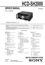
...HCD-SH2000
SERVICE MANUAL
E Model
Ver. 1.1 2011.09
• HCD-SH2000 is the tuner, USB, CD and amplifier section in FST-SH2000/LBT-SH2000.
• "WALKMAN" and "WALKMAN" logo are registered trademarks of Sony Corporation. • MPEG Layer-3 audio...African model
MINI HI-FI COMPONENT SYSTEM
9-890-576-02 2011I08-1 © 2011.09
Sony Corporation
Published by Sony EMCS (Malaysia) PG ...
Service Manual - Page 2
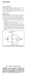
...Earth Ground Fig. SAFETY-RELATED COMPONENT WARNING! REPLACE THESE COMPONENTS WITH SONY PARTS WHOSE PART NUMBERS APPEAR AS SHOWN IN THIS MANUAL OR IN SUPPLEMENTS PUBLISHED BY SONY.
2 A commercial leakage ...
COMPONENTS IDENTIFIED BY MARK 0 OR DOTTED LINE WITH MARK 0 ON THE SCHEMATIC DIAGRAMS AND IN THE PARTS LIST ARE CRITICAL TO SAFE OPERATION. HCD-SH2000
SAFETY...SH-63Trd are suitable. (See Fig.
Service Manual - Page 3
...EXPLODED VIEWS 6-1. Front Panel Section (1 66 6-3. HCD-SH2000
TABLE OF CONTENTS
1. DAMP Board, MAIN Board ... REGULATOR 10
3. MAIN Section 16 5-3. Block Diagram - MAIN Board (Component Side) (Suffix 12 22 5-8. Schematic Diagram - Schematic Diagram ...Schematic Diagram - VOLUME Board 45 5-31. Printed Wiring Boards - AUDIO-IN Board 51 5-38. Back Panel Section 67 6-4. DMB21 ...
Service Manual - Page 4
...that conforms to ISO 9660 2) Level 1/Level 2, Joliet (in hazardous radiation exposure. MP3 audio tracks must be added to ordinary solder. When these parts on the DMB21 board are ... not to apply force on the rear exterior. HCD-SH2000
Ver. 1.1
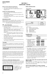
SECTION 1 SERVICING NOTES
Notes on chip component replacement • Never reuse a disconnected chip component. • Notice that the minus side of ...
Service Manual - Page 5
... after distinguishing each type set to doing the repair referring to "SECTION 2 DISASSEMBLY". HCD-SH2000
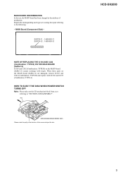
5 MAIN BOARD DISCRIMINATION In this set, the MAIN board has been changed in the direction of production. disc
- CD mechanism block bottom view -
MAIN Board (Component Side) -
SUFFIX-11 : 1-883-863-11 SUFFIX-12 : 1-883-863-12
NOTE...
Service Manual - Page 11
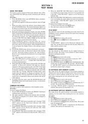
SECTION 3 TEST MODE
HCD-SH2000
PANEL TEST MODE This mode is pressed, "K" value increases. Procedure: 1. Press [SEARCH] ...a message "GEQ MIN" appears on the fluorescent indicator tube.
5. Execute this mode, press @/1 button. 2. A message "MECHA LOCK" is turned counterclockwise even slightly, the sound volume decreases to the customer. Press @/1 button to TV and the volume is enforced ...
Service Manual - Page 12
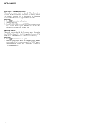
... the factory use preset frequencies into FM 1-FM 20 and AM 1-AM 10. Procedure: 1. The message "LOCKED" or "UNLOCKED" displayed on the system. 2. Press [SEARCH] button and [TUNER/BAND] button simultaneously and hold for 3 seconds. HCD-SH2000
DISC THEFT PREVENTION MODE This mode let prevent disc to be displayed on the fluorescent...
Service Manual - Page 14
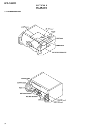
HCD-SH2000
• Circuit Boards Location
SECTION 5 DIAGRAMS
DAMP board
MS-214 board TUNER MAIN board
DMB21 board SWITCHING REGULATOR
DISPLAY board BUTTON board
MIC board
BUTTON LED board VOLUME LED board USB board
VOLUME board AUDIO-IN board
14
Service Manual - Page 16
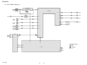
BLOCK DIAGRAM - SIGNAL PATH
: AUDIO : TUNER (FM/AM) : MIC
HCD-SH2000
16
16 J1300 MIC IN
A (Page 15)
L-OUT
J1200
TV R-CH
J1201
PC
GAME AUDIO IN
DVD/SAT AUDIO IN
J500 L R L R
R-CH R-CH R-CH
IC1300 MIC AMP
5
7
3
1
RV1300
MIC LEVEL MIN MAX
IC501 OP AMP
5
7
46 MIC
... 10 XC-OUT 11
X113 8MHz
X110 32.768kHz
R-ch is omitted due to same as L-ch.
MAIN Section - HCD-SH2000
5-2.
Service Manual - Page 17
... INPUT+ OUTPUT 1
MUTE Q600
OP AMP IC600
5 INPUT+ OUTPUT 7
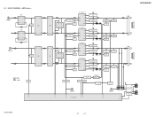
SIGNAL PATH
: AUDIO
MUTE Q207
51
/LINE-MUTE DAMP-CLK /DAMP-RESET
NO USE /SD-SLOW RESONANCE
D1403 D1435
HCD-SH2000
LOW SPEAKER IMPEDANCE USE 4ȍ
2 INA- AOUT 1
PREAMP IC1404
5 INB+ BOUT ...
DAMP FAN
M102 DC FAN
75
FAN LOCK DETECT
Q1447
SMPS FAN
FAN-EN 60
/FAN-LOCK 61
HCD-SH2000
17
17
AMP Section - BLOCK DIAGRAM -
Service Manual - Page 19

...Boards and Schematic Diagrams
Note on Printed Wiring Board:
• X : parts extracted from the component side.
•
: parts extracted from the conductor side.
•
: Pattern from the ...MX : Mexican model MY : Malaysia model SAF : South African model
HCD-SH2000
19
19
HCD-SH2000
Ver. 1.1 F : AUDIO E : USB f : TUNER J : AUDIO (DIGITAL)
• Abbreviation E2 : 120 V AC area in &#...
Service Manual - Page 20

MAIN BOARD (Component Side) (Suffix-11) - • See page 14 for how to distinguish SUFFIX-11 and SUFFIX-12. C345
USB
C BOARD NO1152 (Page 47)
VOLUME
A BOARD CN1000 (Page 45)
AUDIO-IN
H BOARD NO1200 (Page 51)
11 (11)
CN704
CN705
(CHASSIS)
G
DAMP BOARD CN1400 (Page 37)
B
DAMP BOARD CN1401 (Page 37)
J
HCD-SH2000
20...
Service Manual - Page 22

...with single. HCD-SH2000
5-7. C345
USB
C BOARD NO1152 (Page 47)
VOLUME
A BOARD CN1000 (Page 45)
AUDIO-IN
H ...HCD-SH2000
Note 1: Refer to distinguish SUFFIX-11 and SUFFIX-12.
Note 2: A part of circuit composition of production. When these parts on the MAIN board (Suffix-12) cannot exchange with IC102 and C239 (Combination: TYPE A). PRINTED WIRING BOARDS - MAIN BOARD (Component...
Service Manual - Page 24
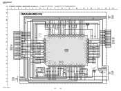
... 100
IC100
SYSTEM CONTROL IC100
R5F3650KBDFA
12
0 JL150 50
0
AUDIO-CLK 49
JL149
0 48
JL148
0 AUDIO-DATA 47
JL147
0 FLASH-MEMORY 46
JL146
HUB-VBUS-DET 45...
8
PCONT (SUB) PCONT (MAIN) AC-DET S/ D-FAST DBFB FAN-EN FAN-LOCK
49 26 71
47 69 70
45 75 44 43
JL513 JL504 JL503 JL502 JL501 JL500...
12
58
13
HCD-SH2000
24
24 HCD-SH2000
Ver. 1.1
5-9. EA 4.7k - SCHEMATIC DIAGRAM -
Service Manual - Page 27

... 820p 50V
DSP-CLK 2 DSP-DATA 1
JL732 R745 JL731 R744
0 78 0 77
HCD-SH2000
27
27 OUTPUT INPUT+ INPUTGND INPUT+
IC503 BPF BA4558F
BB1L BB2L OUTL AGCOUTL AGCC SWOUT CLK... DATA AGCOUTR OUTR BB2R BB1R VOLINR TONEOUTR
15k
GAME IN-L
R739 27k
GAME
AUDIO IN
WHT
RED
L
R
C
D
MAIN
3
2 BOARD
1
(1/4)
2
(Page 24)
IC503
C694
R696
R698
R688...
Service Manual - Page 28

... CONTROL IC100
R5F3650KBDFA
12
0 JL150 50
0
AUDIO-CLK 49
JL149
0 JL148 48
0 AUDIO-DATA 47
JL147
0 FLASH-MEMORY 46
JL146...SUB) PCONT (MAIN) AC-DET S/ D-FAST DBFB FAN-EN FAN-LOCK
49 26 71
47 69 70
45 75 44
JL513 JL504 JL503 JL502...
MAIN
3 BOARD (3/4) (Page 30)
12
58
13
HCD-SH2000
28
28 SAF, EA 1k - SAF 1k - EA 4.7k - HCD-SH2000
Ver. 1.1
5-13. MAIN BOARD (1/4) (Suffix...
Service Manual - Page 31

...12) - • See page 54 for IC Block Diagrams.
1
2
3
4
5
6
7
8
HCD-SH2000
9
10
11
12
13
14
15
A
MAIN BOARD (4/4)
29
R857
0
27
MAIN
26
6 BOARD
... BA4558F
BB1L BB2L OUTL AGCOUTL AGCC SWOUT CLK DATA AGCOUTR OUTR BB2R BB1R VOLINR TONEOUTR
15k
GAME IN-L
R739 27k
GAME
AUDIO IN
WHT
RED
L
R
C
D
MAIN
3
2 BOARD
1
(1/4)
2
(Page 28)
IC503
C694
R696
R698
R688...
Service Manual - Page 32

...) - • See page 14 for Circuit Boards Location. • : Uses unleaded solder.
1
2
3
4
5
6
7
8
9
10
11
12
13
14
15
A B C D E F G H I
J
HCD-SH2000
DMB21 BOARD (Component side) NC
(CHASSIS)
MAIN
I BOARD
CN702 (Page 20) (Suffix 11) (Page 22) (Suffix 12)
MAIN
F BOARD
CN701 (Page 20) (Suffix 11) (Page 22) (Suffix 12)
(...
Service Manual - Page 64

...clock signal output to the A/D converter and D/A converter O Audio data output to the D/A converter
- Ground terminal
O Bank address...supply terminal (+3.3V)
O Component video (Y) signal output terminal Not used O Component video (Pb/Cb) signal output terminal Not used O Component video (Pr/Cr) ...supply terminal (+3.3V) I Full scale adjustment terminal
- HCD-SH2000
Pin No. 69 to 74
75 76 77 78 79...
Service Manual - Page 70

...for safety. Description
AUDIO-IN BOARD
Remark
Ref.
Part No. METAL OXIDE: Metal oxide-film resistor. No. HCD-SH2000
Ver. 1.1 AUDIO-IN BUTTON
BUTTON.... . , uPD. . : μPD. .
• CAPACITORS uF: μF
• COILS uH: μH
The components identified by reference number, please include the board name.
• Abbreviation E2 : 120V AC area in ohms. METAL: Metal...
Similar Questions


How Do Deactivate Child Lock/how To Unlock Child Lock
(Posted by Dumsanmotsa 2 years ago)


Spend All This $$ On This Stereo & Somehow My Grandson Turned On Child Lock,
I figured out how to shut the child lock off but it will not stay off,
I figured out how to shut the child lock off but it will not stay off,
(Posted by gibbslinda97 6 years ago)

How Do I Turn Off The Child Lock On The Sony Hcd-sh2000 Stereo System
(Posted by blueyez5808 10 years ago)