
Sharp CD-E55 Support Question
Sharp CD-E55 Support Question
Find answers below for this question about Sharp CD-E55.Need a Sharp CD-E55 manual? We have 1 online manual for this item!
Question posted by cellefsen on June 28th, 2011
Protection
The radio shuts off after 10 minutes and says proctected.
Current Answers
Related Sharp CD-E55 Manual Pages
Service Manual - Page 1
... VIEW PACKING OF THE SET (FOR U.S.A.
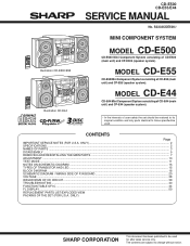
CD-E500 CD-E55/E44
SERVICE MANUAL
No. MODEL CD-E55
CD-E55 Mini Component System consisting of CD-E500 (main unit) and CP-E500 (speaker system). S3333CDE500//
Illustration CD-E500/E55 Illustration CD-E44
MINI COMPONENT SYSTEM
MODEL CD-E500
CD-E500 Mini Component System consisting of CD-E55 (main unit) and CP-E55 (speaker system). The contents are...
Service Manual - Page 2
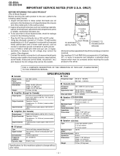
...50 W + 50 W) (10 % T.H.D.)
Speakers: 8 ohms
Headphones: 16 - 50 ohms (recommended: 32 ohms)
Video/Auxiliary (audio signal): 500 mV/47 k ohms
s CD player
Type Signal readout
D/A ...dB (TAPE 2, recording/playback) 0.3 % (WRMS)
s Speaker (CD-E500/E55)
Type
Maximum input power Rated input power Impedance Dimensions
Weight
Twin-drive speaker system 4" (10 cm) woofer 2 100 W
50 W 8 ohms Width: 7-7/8" ...
Service Manual - Page 3
... Up Button
24 25
CD-E500/E55
12
3
10 11
1
2 3
1 2 1
45 67 8 9
12 13
4 5
2
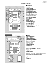
s Display
1.
s Speaker system
1. 1
2 3 4 5 6 7 8 9 10 11
18 19 20 21
NAMES OF PARTS
CD-E500 CD-E55/E44
s Front panel
1. Timer Set Indicator
3. Disc Number Indicators 2. FM Stereo Receiving Indicator 6. CD Button
17
19. Cooling Fan 3. CD or Tape Stop Button
21. CD Pause Indicator 11...
Service Manual - Page 4
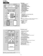
... (Audio Signal) Input Jacks 2. Remote Control Transmitter
2. Power On/Stand-by Button
2
11
3. Program Clear Button
4
13
7. CD or Tape Stop Button
15
10. CD Random...Button
3
12
5. FM Stereo Receiving Indicator 6. s Speaker system
1. CD Pause Button
20. Cooling Fan 3. Bass Reflex Ducts 3. CD-E500 CD-E55/E44
CD-E44
12
3
10 11
1
2 3
1
2
2
3
45 67 8 9
12...
Service Manual - Page 5
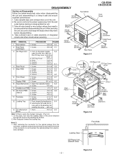
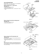
...CD Player Unit (Bottom View)
- 5 - Screw E1) x3 5-2 2. Solder K3) x2
11 Turntable
1. Note 2: 1. After removing the connector for the optical pickup from electrostatic damage. DISASSEMBLY
CD-E500 CD-E55... x8 5-1
3 CD Player Unit
1. Socket C4) x2 6-1
4 Rear Panel
1. After servicing the unit, be sure to rearrange the leads where they need to protect the optical pickup ...
Service Manual - Page 6
...
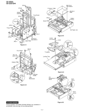
(H1)x8 ø3x8mm
Open
(J1)x1 ø2.5x10mm
Headphones PWB Holder PWB
Figure 6-2
Cassette Holder
Tape Mechanism
Figure 6-4
CD Mechanism Block
Hook (N1)x1
Pull
CP-E500/E55/E44 These speakers CP-E500,CP-E55,CP-E44 are available in assembles only and may not be disassembled.
- 6 - Figure 6-5
Hook (N1)x1
Pull
Service Manual - Page 7
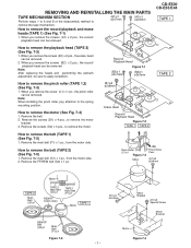
... belt (G2) x 1 pc.
Remove the screws (D2) x 3 pcs., to remove the motor.
(B1)x2 ø2x8mm
Erase Head Record/ Playback Head Figure 7-2 TAPE 1 TAPE 2
CD-E500 CD-E55/E44
TAPE 1
TAPE 2
How to the spring mounting position. Remove the main belt (G1) x 1 pc., from the motor side. Pinch Roller (C1)x1
Figure 7-3
Motor...
Service Manual - Page 8
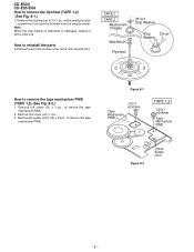
... tape mechanism PWB.
2. Figure 8-1
Tape Mechanism PWB
(J1)x1 ø2x3mm
TAPE 1,2
(J2)x1 ø2x8mm
Tape Mechanism PWB
Figure 8-2
(J3)x2 Solder Joint
- 8 - CD-E500 CD-E55/E44 How to extract the flywheel from the capstan metal. Remove the screw (J2) x 1 pc. 3.
How to remove the tape mechanism PWB (TAPE 1,2) (See Fig...
Service Manual - Page 9
... Figs. 9-1)
1. Remove the belt (B2) x 1 pc. Figure 9-2
Holder PWB
(C1)x4 ø2.5x10mm
Holder CD Mechanism Unit Figure 9-3 CD PLAYER SECTION
Perform steps 1, 2, 3, 10,11, and 12 of connector so as to protect the optical pickup from electrostatic damage.
- 9 - CD-E500 CD-E55/E44
Loading Tray
(A1)x2 ø2.4x3mm
(A2)x1
T/T Motor PWB
(A3)x2 ø...
Service Manual - Page 10
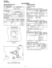
... resistance: 8 ohms)
Test Stage Frequency Frequency Display
Setting/ Instrument Adjusting Connection
Point
FM Band - former T304
fully counter- Input: Antenna Output: TP301 *2.
Figure 10-2 ADJUSTMENT POINTS
- 10 - CD-E500 CD-E55/E44
ADJUSTMENT
MECHANISM SECTION
TUNER SECTION
• Driving Force Check Torque Meter
Play: DM-300
Specified Value
Tape 1: Over 80 g Tape 2: Over 80 g
fL...
Service Manual - Page 12
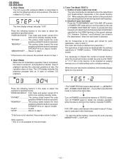
... preset and store frequency for each destination, refer to protect the memory of destination specified by the use of "POWER... Mode (TEST 2) 1. The operations of tuner (radio) test mode The tuner test mode is turned off to
shift to...AC cord, pressing MEMORY/SET + CD PLAY.
- 12 - Step 4 Mode The CLV servo ON command (8600) is ended; CD-E500 CD-E55/E44
4. Press the following display...
Service Manual - Page 14
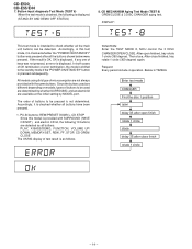
...the "POWER ON/STAND BY" button is pressed subsequently. Below is obtained, the following 10 buttons are available at the initial setting by MODEL port. Button input diagnosis Test Mode...degree) again. FUNCTION: Enter the TEST MODE 8, MCU control the 3 DISC CHANGER OPEN/CLOSE. CD-E500 CD-E55/E44
7. CD MECHANISM Aging Test Mode (TEST 8) OPEN/CLOSE & 3 DISC CHANGER aging test. DISPLAY:
This ...
Service Manual - Page 17
... D_GND DO DI CL M_GND +7V D_GND
+B5
SYSTEM MUTE
Q101 Q102
SO601 VIDEO/AUX IN
AUX L 9 R 16
TAPE L 10 R 15
TUNER L 11 R 14
CD L 12 R 13
DI 1
CE 2
IC601
CL 24
LC75341M
21 R
AUDIO PROCESSOR 4 L
7 8 17 18 3 23
+B2
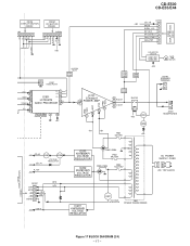
IC101 STK40207 L 15 POWER AMP. R1
12 9 8 4
+B1
-B1
PRE +VCC
+VCC -VCC...
Service Manual - Page 19

...CD-E500 CD-E55/E44
CNS901 3.8V
VF1 1 VF2 2 3.8V -B2 3 -30V +B3 4 5.6V D_GND 5
CNS405 UP_SW 1 DOWN_SW 2 OPEN_SW 3 DISC NO._SW 4 DISC 1_SW 5 CLOSE_SW 6 ROTATE 7
CE 8 CD RES 9
DRF 10 VWRQ 11
CNS803 TAPE_SW 1 T2_RUN_PLUS 2
T2_SOL 3 T1_SOL 4 T1_RUN_PLUS 5 CH_SW 6 MOTOR 7 TAPE_BIAS 8 REC_PLAY 9 REC SW 10
CNS102 FAN_PRT 7 FAN_START 6 SP_DETECT 5 SP_RELAY 4 SIGAL_LVL 3 P_MUTE 2
CD...SIGAL_LVL P_MUTE CD+B D1...
Service Manual - Page 25
... PWB-B4
2.2/16
0.0027 C613 0.1(CH)
C609 2.2/50
C611
R606 1K R608 1K R628 1K C607 4.7/50
R624 12K R625 12K
CD R TUN R TAPE R
C606 10/16
R604 1K
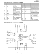
IC601 LC75341M
AUDIO PROCESSOR
R1 L1 R2 L2 R3 L3 R4 L4 RSL0 LSL0 RIN LIN RTRE LTRE RBS LBS ROUTLOUT VREF VSS VDD...
Service Manual - Page 47
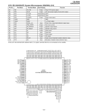
...23
Input signal pin.
24
Terminal Name R1-4 RSEL0 RIN RTRE
RBASS ROUT
VREF
VDD CLK
CD-E500 CD-E55/E44
Function
Input signal pin. Input selector output pin. Supply pin Serial data and clock input ... and AWSS (VSS) as a countermeasure against power ripple. IC601 VHiLC75341M-1: Audio Processor (LC75341M)
LSEL0 LIN LTRE LBASS LOUT
L4 9 CD L3 10 Tuner L2 11 Tape L1 12 Video
R1 13 R2 14 R3 15 R4...
Service Manual - Page 48
...Output Open
10*
P37
PROG2
Input/Output Open
11
RES
RESET IN PUT
Input
Reset signal input.
12*
XT1
XT1
Input
Open
13*
XT2
XT2
Input/Output Open
14
VSS1
GND
-
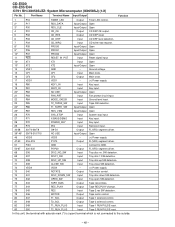
CD-E500 CD-E55/E44 IC701...Input
Key input.
20*
P82
NO USE
Input/Output Open
21
P83
FAN_PRT
Input
Fan protect circuit input.
22
P84
MODE_CKECK
Input
Ground level input.
23
P85
T2_TAPE2_SW
Input
Tape SW...
Service Manual - Page 49
.... Input
Broadcast reception status detection input. Output Speaker output detect. Output Speaker relay control. Output Data output. Input
Radio stereo broadcast reception detection input.
output level detection signal input.
FIX 0
S2 0 / PC4
S2 1 / PC5... to the outside.
Port Name
Terminal Name Input/Output
Function
CD-E500 CD-E55/E44
84
S51
85
P00
86*
P01
87*
P02
88...
Service Manual - Page 51
... CD-E55
CD-E55 Mini Component System consisting of CD-E44 (main unit) and CP-E44 (speaker system). MODEL NUMBER
2.
For U.S.A. The 13th character represents capacity difference.
("J" ±5%, "K" ±10%, "M" ±20%, "N" ±30%, "C" ±0.25 pF, "D" ±0.5 pF, "Z" +80-20%.)
If there are no indications for maintaining the safety of the set . CAUTION:FOR CONTINUED PROTECTION...
Service Manual - Page 60
No part of the publisher.
CD-E500 CD-E55/E44
COPYRIGHT © 2003 BY SHARP CORPORATION
ALL RIGHTS RESERVED.
SHARP CORPORATION AV Systems Group Audio Systems Division Higashihiroshima, Hiroshima 739-0192, Japan
Printed in any form or by any means, electronic, mechanical, photocopying, recording, or otherwise, without prior written permission ...
Similar Questions


Looking For An Antenna For My Sharp Cd-e55 Mini Component System
I need a replacement antenna for my CD-E55 Mini Component System.
I need a replacement antenna for my CD-E55 Mini Component System.
(Posted by hermanmoore01 10 years ago)


How To Disable Sleep Mode On Cd-dh950p
How to disable sleep mode on Sharp CD-DH950P radio without a remote?
How to disable sleep mode on Sharp CD-DH950P radio without a remote?
(Posted by kmptbi 11 years ago)