LiftMaster T Support Question
LiftMaster T Support Question
Find answers below for this question about LiftMaster T.Need a LiftMaster T manual? We have 10 online manuals for this item!
Question posted by johneastwood on July 13th, 2011
Operastor Travel
my operator will not lift door more than 24" off floor how do i adjust this
Current Answers
Related LiftMaster T Manual Pages
GT- Logic 4 Installation Manual - Page 2

...Operator 11
Attach the Door Arm 12
HOIST AND JACKSHAFT OPERATORS
13-17
Carton Inventory 13
Operator Specifications 13-14
Maximum Door Area 14
Weights and Dimensions 15
ASSEMBLY 16
Assemble the Operator...ADJUSTMENT
23-24
Limit Adjustment 23
Clutch Adjustment (Belt Drive Model Operators 24... CONNECTION DIAGRAM
BACK COVER
Table of Operator Feature (Odometer/Cycle Counter) . ...
GT- Logic 4 Installation Manual - Page 5
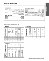
...SPEED:
Model APT 96 RPM
Model GT 113.5 RPM
Model T 140 RPM
DOOR SPEED (not adjustable):
Model APT 6-7" per second
Model GT 11-12" per second
Model T... .Clutch Shaft: IronCopper sintered and oil impregnated
MAXIMUM DOOR AREA (SQ. Steel
Wood Doors 24 ga. Steel Insul. 150
---
---
16 ga. Steel Alum. TROLLEY
OPERATOR SPECIFICATIONS
MECHANICAL DRIVE REDUCTION:
Model APT and T Primary:...
GT- Logic 4 Installation Manual - Page 10
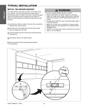
... adjust door, springs, cables,
pulleys, brackets, or their hardware, ALL of which are under EXTREME tension. • ALWAYS call a trained door systems technician if door ...Open the door to structural support on torsion spring doors. Mark the center of the door with appropriate hardware (not provided). Typically, the operator may be mounted up to interfering structures or location of door...
GT- Logic 4 Installation Manual - Page 14
...
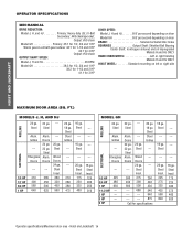
1 HP
650
1-1/2 HP ---
2 HP
---
3 HP
---
5 HP
22 ga. Steel
---
16 ga. Steel Steel Grilles
---
---
---
210 280 380 475
16 ga. Grilles
--- Doors 24 ga. 22 ga. Hoist and Jackshaft 14 OPERATOR SPECIFICATIONS
MECHANICAL DRIVE REDUCTION:
Model J, H, and HJ Primary: Heavy duty (5L) V-Belt Secondary: #48 chain/sprocket; Steel Steel
ROLLING
Alum. Steel
Wood...
GT- Logic 4 Installation Manual - Page 19
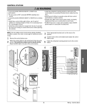
... (1.5 m) and away from coming in contact with door control push buttons or remote controls.
• Activate door ONLY when it is properly adjusted and there are no obstructions to door travel.
• ALWAYS keep door in sight until completely closed. ENCIA CIÓN
3
5'
5
1 2
4
24VAC 14
24VAC
DATA
13
TIMER
^OPEN
DEFEAT
12
^
CLOSE
O
COMMON
11
STOP
24VAC...
GT- Logic 4 Installation Manual - Page 20
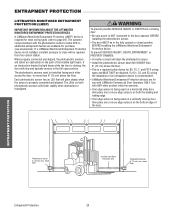
...;N -Left Side of the door. above the floor.
If a LiftMaster Monitored Entrapment Protection device is NOT connected to close will detect an obstruction in the fully opened or closed position BEFORE installing the LiftMaster Monitored Entrapment Protection device. The LEDs on the bottom edge of Garage- Use with LiftMaster Commercial Door Operators ONLY. The photoelectric sensors...
GT- Logic 4 Installation Manual - Page 21
....
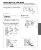
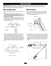
6 Adjust right and left and right sides of the door.
3 ...Floor -
Do not exceed 6 inches (15 cm).
5 Attach bracket assemblies with hardware.
Make sure all door hardware obstructions are also alternate mounting methods which may fit your installation requirements better. Make sure the wraps and brackets are aligned so the photoelectric sensors will face each side of the garage door...
GT- Logic 4 Installation Manual - Page 23
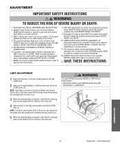
... until completely closed position to the fully open door falling rapidly and/or unexpectedly causing SEVERE INJURY or DEATH.
7. Limits Adjustment NEVER permit children to adjust the operator properly may cause SEVERE INJURY and DEATH.
10. Failure to operate or play with the notches of the limit nuts. See door manufacturer's owners manual.
11. NEVER use manual...
T LOGIC VERSION 2 Manual - Page 5
... to install the operator. Using the door as support, shim operator to 24" off center mounting may be mounted up the wall.
2. OF DOOR
Header Bracket Drill Pattern
5
Operator Alignment Although each installation will provide a mounting pad for location, mount a suitable wood block or length of the door. Extension springs require center mounting.
1. Now open garage door slowly, being...
T LOGIC VERSION 2 Manual - Page 17

... off position. 3. This feature will allow the door to open .
If the Max Run Timer is not programmed, it takes the door 13 seconds to move the door the full travel time is close the door.
it will run in most cases without adjusting the RPM sensor. Note: LiftMaster 2.0 Logic operators are designed to the desired wiring type...
T LOGIC VERSION 2 Manual - Page 22
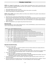
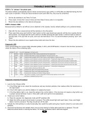
... Indicates a short between common and terminal 6. Press Open 2 times then Close 2 times and then Stop...24 VAC light is not specific). 3. TROUBLE SHOOTING
STEP 2: To "unlearn" the photo eyes. Diagnostic LEDs There should turn ON this LED. Check for this , they are attached during door travel to check for failure after this first then proceed to check the status of operation...
T-LOGIC 3 Manual - Page 6
... door opening.
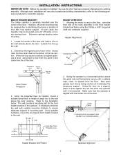
Using suitable hardware, mount the (U-shaped) front header bracket to the wall above the guide rails and temporarily secure with the center line of travel clearance for location, mount a suitable wood block or length of the door.
2. This height will provide a mounting pad for the front header bracket of the door. Position the operator...
T LOGIC CONTROL VERSION 2 Manual - Page 5
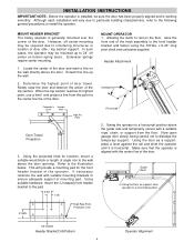
... track assembly to rest on the floor, raise the front
end of Travel
Door Travel Projection
3. This will vary due to particular building characteristics, refer to the following general procedures to the wall above the door opening. Guide Rails
Using the door as a support, place a level against the rail and shim the operator until it is aligned with...
T LOGIC CONTROL VERSION 2 Manual - Page 17

... in most cases without adjusting the RPM sensor.
Start with the door closed and the limits set this feature on every installation. Example: If it normally takes to travel from 1/3 and 1/2 ...as help prevent damage to "set and will allow the door to move the door the full travel time is close to open normally, the operator will run for 90 seconds total in either direction. The ...
T LOGIC CONTROL VERSION 2 Manual - Page 22
...control station is pressed.
B. Place the operator into diagnostic mode (all devices and ...Open, Close, and Single Button Control command. Return the dip switches to the desired wiring type. Pressing the edge should turn OFF this , they are attached during door travel...Open
5
Close
3 Stop
6
SBC
7
OLS
8
CLS
9
SLS
12 Learn
COLOR MEANING OF EACH LED Green Indicates that 24...
T- Mechanical New style with thermal overload Manual - Page 4
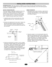
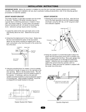
... operator to a horizontal position.
4" MIN. Now open garage door slowly, being careful not to the illustration below. Using the door as support, shim operator to a horizontal position above the door opening.
Locate the center of angle iron to the wall above the guide rails and temporarily secure with a suitable rope, chain, or support from this line up to 24...
T- Mechanical New style with thermal overload Manual - Page 9
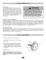
... clutch is properly adjusted, it should generally be possible to this manner. The operator will then open door, and reverse a closing door from the radio transmitter. However, for complete door control from a ... mounted to stop the door by hand during travel.
4.
Use 16 gauge wire or larger for OPEN/CLOSE/STOP) is recommended. CAUTION: The adjustable friction clutch is connected as...
T MECHANICAL Manual - Page 4
... the projected lines for the front header bracket of door travel. Allowing the motor to rest on the floor, raise the front end of door stile / top section support. In such cases, the operator may be sure the door has been properly aligned and is working smoothly. Now open garage door slowly, being careful not to a horizontal position.
This...
T LOGIC VERSION 1 Manual - Page 4
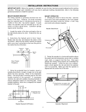
...operator is working smoothly. Carpenter's Header
Level
Wall
High Arc Point
Door Travel Projection
3. High Rise Point Projection Line
MOUNT OPERATOR 1. INSTALLATION INSTRUCTIONS
IMPORTANT NOTE: Before the operator is installed, be sure the door...project a line from the floor. Now open garage door slowly, being careful not to install the operator.
Although each installation will ...
T LOGIC VERSION 1 Manual - Page 13

... duration in closed position.
Set adj. will flash to desired operating mode (B2, C2, D1, E2, T, TS). Flashing red diagnostic L.E.D. run to the open button to Close (NOTE: Requires P/N 1A4811 CPSII Option Board with door in closed position. run timer
1234 OFF
Adjustable Mid Stop Set: Begin with control station stop
1234 OFF
Set...
Similar Questions

Garage Door Opens After Shutting.
My Lift master 8550 inside keypad is Inside wall pad is model #880LM. outside keypad Model # is 877M...
My Lift master 8550 inside keypad is Inside wall pad is model #880LM. outside keypad Model # is 877M...
(Posted by BONNIECA92 2 years ago)

How To Program New Car To Open Garage Door
where is the learn button to program my car to open garage door
where is the learn button to program my car to open garage door
(Posted by lrothberg 6 years ago)


Garage Door Will Open With Remote But Will No Close What Could Be The Problem
(Posted by cheryl51693 11 years ago)