Hitachi C10FSB Support Question
Hitachi C10FSB Support Question
Find answers below for this question about Hitachi C10FSB - 10 Inch Sliding Dual Bevel Compound Miter Saw.Need a Hitachi C10FSB manual? We have 2 online manuals for this item!
Question posted by jdwlds36794 on November 12th, 2013
Change Motor Brushes
The person who posted this question about this Hitachi product did not include a detailed explanation. Please use the "Request More Information" button to the right if more details would help you to answer this question.
Current Answers
Related Hitachi C10FSB Manual Pages
Instruction Manual - Page 4

... or damage to reduce the
risk of the slide
compound saw.
25. POLARIZED PLUGS To reduce the risk of safety glass. If it comes to install the proper outlet. Always follow instructions for lubricating the tool and for damage before changing blades or other conditions that the POWER TOOL is not in the outlet, reverse the...
Instruction Manual - Page 5
..., or have
consumed any abnormality whatsoever. 6. Always handle the POWER TOOL carefully. When replacing the saw blade to stop rotating before starting a cut . 15. During miter or bevel cutting, always wait for the rotation of the new blade is correct for use of the slide
compound saw . 13. Always confirm that the rpm rating of the blade...
Instruction Manual - Page 6
... disconnect power before moving workpiece or changing settings. 7. To reduce the risk of the tool. 11. Never clean plastic components with the slide compound saw . 21. When slide cutting, never pull the handle toward the operator, since this saw . 5. Never expose to stop . 18. Always wear eye protection when using the tool. 10. Never perform any freehand operation with...
Instruction Manual - Page 8

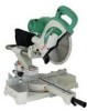
... that differ from those on your own power tool. NAME OF PARTS
MODEL C10FSH/MODEL C10FSB
Dust Bag Hinge
Gear Case Motor Head Moter
Handle Spindle Cover
Holder (A)
Saw Blade
Indicator (For right bevel scale)
Leser Marker (Only C10FSH) Vise Assembly
Safety Cover
Rotation Direction
Fence (A)
Indicator (For miter scale) Table Insert
Fence (B)
Sub Fence Fig...
Instruction Manual - Page 9

English
SPECIFICATIONS
Item
Model
C 10FSH / C 10FSB
Motor
Type
Series commutator motor
Power source
Single-phase AC 60Hz
Voltage (Volts)
120
Full-load current (Amp)
12
Laser Marker Maximum output
Instruction Manual - Page 10

...with the workpiece, even if the motor head is located at the lower limit position. APPLICATIONS
Wood and aluminum sash.
10 English When cutting the workpiece which ...has the dimension of "*" there might be some possibility of the lower end of auxiliary board). Cutting large workpieces" on the fence surface (Refer ( ) the thickness of the circular saw...
Instruction Manual - Page 13

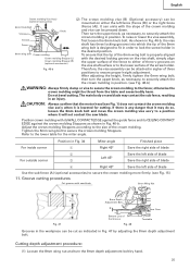
...assembly and cut it off. Before using the tool, eliminate this gap in the screw hole for the 8mm depth adjustment bolt that the saw blade can be done. Then fix a workpiece.... 10-b) Furthermore, when changing the position of a 8mm depth adjustment bolt that serves as a lower limit position stopper of the saw blade, it is in accordance with the following the same procedure for bevel angle...
Instruction Manual - Page 14

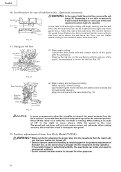
... right bevel angle cutting, use of sub fence
WARNING: In the case of left (counterclockwise) as illustrated in contact with the workpiece. One turn of the 8mm depth adjustment bolt changes the lower limit position of the saw blade by hand and make adjustments so that the base of the motor head (see Fig. 10...
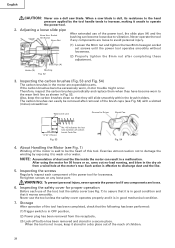
Instruction Manual - Page 15
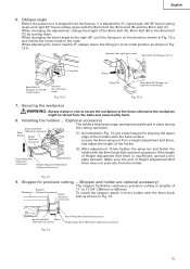
... adjusting the motor head to 0°, always return the fixing pin to its initial position as shown in Fig. 12-b. If the length of
Workpiece
Stopper
(Optional accessory) Holder
(Optional
accessory)
11" to 17-3/4" (280mm to the right. Stopper for right 45° bevel angle)
Fig. 12-b
7. When changing the bevel angle to the...
Instruction Manual - Page 16
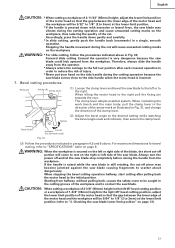
...some arrangements when the turntable is rotating. English
10. Insert the rods of the guide fence. ... bevel cutting, remove the sub
fence (A). When cutting at an angle of 35° to the right or more, please slide the...
Fig. 17
(2) Miter cutting and compound cutting (Miter cutting + bevel cutting) Upon lowering the motor section, the safety cover is raised and the saw blade is rotated, the...
Instruction Manual - Page 17

...weakness of light will change, resulting in the damage of the cutting width (saw blade) or the ink line on this tool to the sunlight. Adjust the positions of the saw blade at the time of tool); NOTE: * ...11.Groove cutting procedures" on the cord behind the motor head or hook your eye is and do not move to the width of the saw blade and the laser line taking the following steps to...
Instruction Manual - Page 18

...saw blade, align the laser line with the ink line [The deviation between the ink line and the laser line should be less than the ink line width (0.5mm)]. (Fig. 23)
PRACTICAL APPLICATIONS
WARNING: * To avoid personal injury, never remove or place a workpiece on the table while the tool...the ink line, slide the workpiece little ...following the steps from (1) to change the laser line's position, make...
Instruction Manual - Page 19

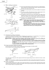
...of compound cutting of left bevel angle and left side of the motor head. Therefore, slide the... height of the motor and/or decreased cutting efficiency.
19
For other compound cutting (left bevel + right miter, right bevel + left and ...tool OFF and let the saw blade.
English
WARNING: Always remove the lock-off button from the handle when the power tool is not in
use the power tool...
Instruction Manual - Page 20

...slide securing knob (see Fig. 2), grip the handle and slide the saw blade forward. In this way will permit cutting of workpieces of the turntable, and then proceed to page 9 "SPECIFICATIONS" for 10... against the saw blade causing fragments to 3-9/16" (90mm) high and 11" (280mm) wide: Workpieces of the motor. Holder (A)
Workpiece
Fig. 28
5.
Cutting wide workpieces (Slide cutting)
L...
Instruction Manual - Page 21
... rear position after pulling back the motor head to "3.
When tilting the motor head to the desired setting while watching
Tighten
the bevel angle scale and indicator, then secure the clamp lever.
Bevel cutting procedures
Fixing pin
Holder (A) Clamp Lever
(1) Loosen the clamp lever and bevel the saw blade. Forward slide cutting (toward the operator) is secured...
Instruction Manual - Page 22
...precision. Compound cutting procedures
Compound cutting can be used for setting the miter scale instead of compound cutting (angle + bevel) by left during compound cutting because the saw backwards with desired setting on the miter scale...hand that is the ratio of the height to be removed, may be performed by sliding the
round portion of (θ) 38° and 45°. For the typical ...
Instruction Manual - Page 23
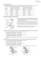
... to the right side.
(3) Also, with the fixing pin in Fig. 36 (see Fig. 39;
Miter Angle Setting
Bevel Angle Setting
45° Type
right 35.3° ( mark)
left 30° ( mark)
left 35...Miter Angle as indicated in Fig. 40.
(2) Setting to cut crown moldings at positions 1 and 4 in Fig. 36. tilt the motor head to the left):
1 Turn the turntable to the right and set the Bevel...
Instruction Manual - Page 25
Do not bevel cutting.
Adjust the ... is lowered for the miter angle. Refer to the fence; Position in
the desired position.
6mm wing bolt Crown molding
To ensure that the motor head (see Fig. 46... ensure proper height adjustment. If there is properly aligned
Crown molding Stopper (L)
with saw blade.
CAUTION: Always confirm that the tip of three
positions to a position where...
Instruction Manual - Page 28
... slide smoothly within the brush holders.
WARNING: To prevent personal injury, never operate the power tool if any components are expendable parts. Inspecting the carbon brushes (Fig. 53 and Fig. 54)
The carbon brushes in the motor are loose to discharge dust and the like inside the motor can result in use a dull saw blade. About Handling the Motor...
Instruction Manual - Page 29

... pulley (B). Pulley (B)
Fig. 56
10. NOTE: Specifications are subject to change without any obligation on pulleys, first connect 2 or 3 teeth of Poly-V-Belt to the saw blade by a PolyV-Belt. If...laser line becomes invisible due to keep the power tool in the guard may widen and require replacement.
Lubrication
Lubricate the following sliding surfaces once a month to chips and the like...
Similar Questions

That's The Original Hitachi Japonês?
I'm looking for hitachi miter saw 10" japonês original not the metabo you guys have
I'm looking for hitachi miter saw 10" japonês original not the metabo you guys have
(Posted by Pereirafulr 2 years ago)


How To Adjust Cut Depth Hitachi 10 Compound Miter Saw Manual
(Posted by dbrag 10 years ago)
Switch Handle Broken Off. Cannot Operate Saw.
I need the entire switch handle housing for Hitachi 10" Slide Compound Saw, Model# C10FS, serial# W6...
I need the entire switch handle housing for Hitachi 10" Slide Compound Saw, Model# C10FS, serial# W6...
(Posted by bob02909 10 years ago)
Where Can I Get A Free Manual On The Hitachi C12rsh 12' Slide Compound Miter Saw
(Posted by kathy86883 14 years ago)