
Dell PowerEdge 2950 Support Question
Dell PowerEdge 2950 Support Question
Find answers below for this question about Dell PowerEdge 2950.Need a Dell PowerEdge 2950 manual? We have 8 online manuals for this item!
Question posted by bltoll on November 8th, 2013
How To Reset System-status Indicators Bios Poweredge 2600
The person who posted this question about this Dell product did not include a detailed explanation. Please use the "Request More Information" button to the right if more details would help you to answer this question.
Current Answers
Related Dell PowerEdge 2950 Manual Pages
Information Update - Page 2
... of your computer. Microsoft, Windows, and Windows Server and are trademarks of Novell Inc.
A07
CAUTION: A CAUTION indicates potential damage to either trademarks or registered trademarks of... these materials in any proprietary interest in this text: Dell, the DELL logo, and PowerEdge are either...
Information Update - Page 3
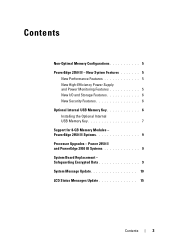
... 6 Optional Internal USB Memory Key 6 Installing the Optional Internal USB Memory Key 7 Support for 8-GB Memory Modules - Power 2950 II and PowerEdge 2950 III Systems 9 System Board Replacement - Safeguarding Encrypted Data 9 System Message Update 10 LCD Status Messages Update 15
Contents
3 PowerEdge 2950 III Systems 9 Processor Upgrades - Contents
Non-Optimal Memory Configurations...
Information Update - Page 9
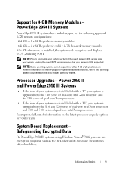
...upgrade options for your system is fully supported. Loading the latest BIOS version ensures that your system. Power 2950 II and PowerEdge 2950 III Systems
• If the front of your system chassis... recognizes and displays 63.75 GB during POST. Safeguarding Encrypted Data
On PowerEdge 2950 III systems using Windows Server® 2008, you can use encryption programs, such as the BitLocker utility...
Information Update - Page 15
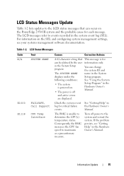
... SYSTEM NAME displays under the following conditions:
• The system is powered on the PowerEdge 2950 III system and the probable cause for each message. The BMC is off power to ...program.
If the problem persists, see your systems management software documentation. Table 1-2. LCD Status Messages
Code N/A
E1000 E1118
Text SYSTEM NAME
FAILSAFE, Call Support CPU Temp Interface
Causes...
Information Update - Page 18
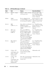
...One of the two indicated See "Troubleshooting
DIMMs has had Owner's Manual. logging further SBEs until
the system is missing or disconnected.
The system BIOS has See "Troubleshooting... with a blue or amber background.)
Causes
Corrective Actions
DRAC 5 cable is restarted.
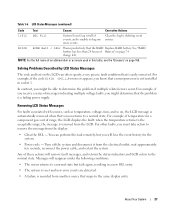
LCD Status Messages (continued)
Code E1914 E1B01 E2110 E2111
E2112
I1915 I1916
Text DRAC5 Conn2 Cbl
USB#...
Information Update - Page 24
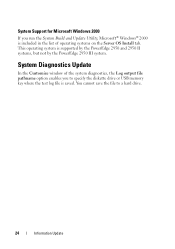
... key where the test log file is saved. System Diagnostics Update
In the Customize window of operating systems on the Server OS Install tab. System Support for Microsoft Windows 2000
If you to a hard drive.
24
Information Update This operating... the System Build and Update Utility, Microsoft® Windows® 2000 is supported by the PowerEdge 2950 and 2950 II systems, but not by the...
Information Update - Page 26
2006 - 2009 Dell Inc
未经 Dell Inc
Dell、 DELL 徽标和 PowerEdge 是 Dell Inc Intel 和 Xeon 是 Intel Corporation Microsoft、 Windows 和 Windows Server 是 Microsoft Corporation Red Hat 和 Red Hat Enterprise Linux 是 Red Hat, Inc SUSE 是 Novell Inc
Dell Inc
2009 年 10...
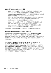
Information Update - Page 46
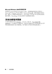
Microsoft Windows 2000
System Build and Update Utility Microsoft® Windows® 2000 将位于 Server OS Install PowerEdge 2950 和 2950 II PowerEdge 2950 III
Customize Log output file pathname USB
46
信息更新
Information Update - Page 132
... Xeon 54xx BIOS で Demand-Based Switching cat/proc/cpuinfo および cat/sys/devices/system/cpu/cpuxx/cpufreq/scaling_ cur_freq
• RHEL 3 9 Intel Xeon 54xx proc/cpuinfo
RHEL 4
Microsoft Windows 2000
System Build and Update Utility Server OS Install OS OS Microsoft® Windows® 2000 PowerEdge 2950/2950 II OS PowerEdge 2950 III
Customize...
Hardware Owner's Manual (PDF) - Page 13

... LCD panel on the front and the blue system status indicator on the back blink until one of a paper clip.
Front-Panel Features and Indicators
1
2
3
4
5
6
7
8
0
2
4
1
3
5
Table 1-2. Front-Panel LED Indicators, Buttons, and Connectors
Item
Indicator, Button, or Connector Icon
1
Power-on indicator, power
button
2
NMI button
3
System identification button
Description
The...
Hardware Owner's Manual (PDF) - Page 15
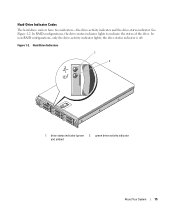
..., the drive-status indicator lights to indicate the status of the drive. Hard-Drive Indicators
1
2
1 drive-status indicator (green 2 green drive-activity indicator and amber)
About Your System
15
Hard-Drive Indicator Codes
The hard-drive carriers have two indicators-the drive-activity indicator and the drive-status indicator. See Figure 1-2. the drive-status indicator is off.
Hardware Owner's Manual (PDF) - Page 16

... for operation" pattern appears, followed by the "drive ready for insertion or removal Drive predicted failure Drive failed Drive rebuilding Drive online Rebuild aborted
Drive-Status Indicator Pattern Blinks green two times per second. Blinks amber four times per second
Off
Blinks green, amber, and off six seconds.
16
About Your System...
Hardware Owner's Manual (PDF) - Page 17

...
10 USB connectors (2)
13 remote access controller (optional)
2 left PCI riser (slot 2) 5 system identification button 8 NIC2 connector
3 left PCI riser (slot 3) 6 system status indicator 9 NIC1 connector
11 video connector
12 serial connector
Connecting External Devices
When connecting external devices to your operating system software or with the device itself.) ...
Hardware Owner's Manual (PDF) - Page 27
... that a microprocessor is not installed in a new SEL entry.
• The system is reset and new error events are detected.
• A failure is easily corrected. charge left. ...
For example, if you receive a series of these actions will remove fault messages, and return the status indicators and LCD colors to a normal state but you might be able to determine the problem if multiple ...
Hardware Owner's Manual (PDF) - Page 64

... the power cable to signify that the power supply is completely flush with the power-supply faceplate and the orange snap engages. The power supply status indicator will turn green to the power supply, and plug the cable into the chassis.
NOTICE: To ensure proper system cooling, the power supply blank must...
Hardware Owner's Manual (PDF) - Page 118
...
118
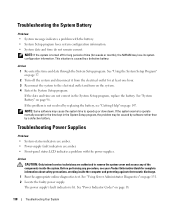
Troubleshooting Your System Troubleshooting Power Supplies
Problem • System-status indicators are amber. • Power-supply fault indicators are amber. • Front-panel status LCD indicates a problem with the battery. • System Setup program loses ... the faulty power supply. See "Using Server Administrator Diagnostics" on the system. 4 Enter the System Setup program.
Hardware Owner's Manual (PDF) - Page 119
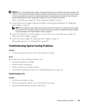
...persists, see if the problem is functioning properly. Troubleshooting a Fan
Problem • System-status indicator is obstructed. • Cables inside the system obstruct airflow. • An individual cooling...• Systems management software issues a fan-related error message. • Front panel LCD indicates a problem with only one power supply at a time in the redundant mode when two...
Rack Installation Guide - Page 9

... rack to other racks. NOTE: Both the right and left cable-management arm ramp assembly • One right cable-management arm ramp assembly • One status indicator cable (if applicable) • Eight 10-32 x 0.5-inch flange-head Phillips screws
NOTE: The nonmetric screws described in illustrations and in procedural steps are illustrated...
Rack Installation Guide - Page 10
...
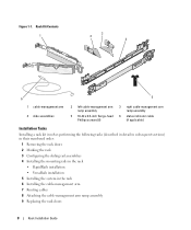
6
5
1 cable-management arm 4 slide assemblies
2 left cable-management arm ramp assembly
5 10-32 x 0.5-inch flange-head Phillips screws (8)
3 right cable-management arm ramp assembly
6 status indicator cable (if applicable)
Installation Tasks
Installing a rack kit involves performing the following tasks (described in detail in subsequent sections) in their numbered order:
1 Removing the ...
Rack Installation Guide - Page 20

... 1-9. For details on cable connections, see Figure 1-9). Routing Cables on the Cable-Management Arm 1
2
1 tie wraps (2) 3 cable-management arm
4
3
2 system status-indicator cable connector 4 wire cable basket
2 If applicable, connect the system status-indicator cable to be routed within the arms (see your system's Getting Started Guide or Hardware Owner's Manual. Routing Cables
1 Open...
Similar Questions

How To Monitor Raid Status On Dell Poweredge 2950 Windows Server 2003
(Posted by incfaust 9 years ago)

How Do I Use The System Status Indicator On Poweredge 2800
(Posted by pierdigib 10 years ago)

How To Check The Raid Battery Status On Dell Poweredge
(Posted by killNOAHX 10 years ago)

