Dell OptiPlex 745 Support Question
Dell OptiPlex 745 Support Question
Find answers below for this question about Dell OptiPlex 745.Need a Dell OptiPlex 745 manual? We have 1 online manual for this item!
Question posted by juljo on October 5th, 2013
Optiplex 745 In A Pre Bios Mode When Powered Up
The person who posted this question about this Dell product did not include a detailed explanation. Please use the "Request More Information" button to the right if more details would help you to answer this question.
Current Answers
Related Dell OptiPlex 745 Manual Pages
Quick Reference
Guide - Page 2

... avoid the problem. Microsoft and Windows are trademarks of Microsoft Corporation. disclaims any references in this text: Dell, the DELL logo, Inspiron, Dell Precision, Dimension, OptiPlex, Latitude, PowerEdge, PowerVault, PowerApp, and Dell OpenManage are registered trademarks of Dell Inc.; All rights reserved. Trademarks used in this document is strictly forbidden. A00...
Quick Reference
Guide - Page 3
...Back View 18 Small Form Factor Computer - Back View 10 Mini Tower Computer - Back View 14 Desktop Computer - Front View 17 Small Form Factor Computer - Back-Panel Connectors 15 Small Form Factor ...Up Your Computer 43 Set Up Your Keyboard and Mouse 45 Set Up Your Monitor 45 Power Connections 46
Solving Problems 46 Dell Diagnostics 46 System Lights 49
Contents
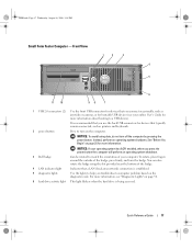
3 Front View ...
Quick Reference
Guide - Page 5
... CD to provide lastminute updates about technical changes to your computer.
Dell™ OptiPlex™ User's Guide
Microsoft Windows XP Help and Support Center 1 Click Start&#...the User's Guide for my computer • My computer documentation • My device documentation • Desktop System Software (DSS)
• How to remove and replace parts • Specifications • How...
Quick Reference
Guide - Page 9
.... Can contain an optional floppy drive or optional media card reader. To exit from a power-saving mode, see your online User's Guide. See your online User's Guide for more information about sleep modes and exiting from a power-saving mode, press the power button or use the back USB connectors for bootable USB devices (see your computer...
Quick Reference
Guide - Page 11
... a parallel device, such as a printer, to the same address. If you have a USB printer, plug it into the appropriate connectors (see your location.
4 power connector
Insert the power cable.
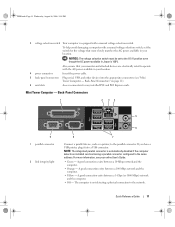
5 back-panel connectors Plug serial, USB, and other devices into a USB connector. For more information, see "Mini Tower Computer - A good connection exists between...
Quick Reference
Guide - Page 13
...USB devices (see your computer. book.book Page 13 Wednesday, August 16, 2006 3:18 PM
Desktop Computer - It is recommended that you use the back USB connectors for devices that typically remain connected... as printers and keyboards.
2 LAN indicator light
This light indicates that you press the power button the computer will perform an operating system shutdown.
4 Dell badge
This badge can ...
Quick Reference
Guide - Page 14
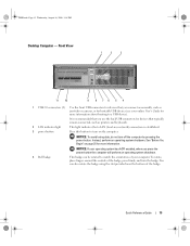
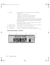
...this drive. Back View
1
2
3
4
5
6
14
Quick Reference Guide To exit from a power-saving mode, see "Diagnostic Lights" on the diagnostic code. Use the lights to indicate different operating states: •...drive or optional Media Card Reader. Desktop Computer -
Can contain an optical drive. book.book Page 14 Wednesday, August 16, 2006 3:18 PM
5 power light
6 diagnostic lights 7 hard...
Quick Reference
Guide - Page 15
... connectors (see "Desktop Computer - Desktop Computer -
book....book Page 15 Wednesday, August 16, 2006 3:18 PM
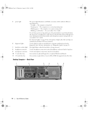
1 card slots
Access connectors for the voltage that your monitor and attached devices are electrically rated to operate with the AC power available in Japan is equipped with a manual voltage selection switch.
Back-Panel Connectors" on page 15).
3 power...
Quick Reference
Guide - Page 17
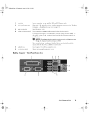
...your online User's Guide for devices that you connect occasionally, such as printers and keyboards.
2 power button
Press to a USB device). Quick Reference Guide
17 book.book Page 17 Wednesday, August ...the outside of the badge, press firmly, and turn off the computer by pressing the power button.
It is recommended that typically remain connected, such as joysticks or cameras, or ...
Quick Reference
Guide - Page 18
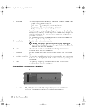
...8226; No light -
Back View
1
2
3
4
5
6
18
Quick Reference Guide
The computer is in a power-saving mode. • Blinking or solid amber - The computer is turned off. • Steady green - See "System ... or optional media card reader.
For more information about sleep modes and exiting from a power-saving mode, press the power button or use the keyboard or the mouse if it is...
Quick Reference
Guide - Page 19

... (see "Small Form Factor Computer -
Small Form Factor Computer - Back-Panel Connectors
1
2 34
9
8
5
6 7
Quick Reference Guide
19 Back-Panel Connectors" on page 19).
3 power connector
Insert the power cable.
4 voltage selection switch Your computer is 100 V.
To help avoid damaging a computer with a manual voltage selection switch, set to open the computer cover...
Quick Reference
Guide - Page 22
... an operating system shutdown. To ensure proper ventilation, do not turn on page 25 for a description of the computer help prevent your computer from a power-saving mode, see your online User's Guide. The computer is on each side of light codes that can help prevent your online User's Guide. The light might...
Quick Reference
Guide - Page 23
.... Quick Reference Guide
23
book.book Page 23 Wednesday, August 16, 2006 3:18 PM
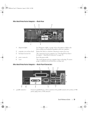
Ultra-Small Form Factor Computer - Insert the power cable. Back View
1
2
3
5
4
1 diagnostic lights
2 computer cover release knob 3 back-panel connectors
4 power connector 5 vents
See "Diagnostic Lights" on page 23). If you troubleshoot problems with your computer from overheating.
Quick Reference
Guide - Page 24
...network adapter connector on the back panel. or a personal computer microphone for the power adapter. If you troubleshoot problems with a network connector card, use Category 3 wiring... a VGA Monitor" in / microphone
connector 7 USB connectors (5) 8 serial connector 9 video connector
10 power connector 11 diagnostic lights
• Green - If you must use the connector on " state. A good...
Quick Reference
Guide - Page 32
book.book Page 32 Wednesday, August 16, 2006 3:18 PM
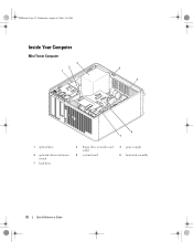
Inside Your Computer
Mini Tower Computer
3 2 1
4 5
6 7
1 optical drive
4 optional chassis-intrusion switch
7 hard drive
2 floppy drive or media card reader
5 system board
3 power supply 6 heat-sink assembly
32
Quick Reference Guide
Quick Reference
Guide - Page 34
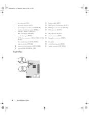
... password jumper (PSWD)
17 serial connector (SER2)
7 SATA drive connectors (SATA0, SATA1, SATA4, 18 floppy drive connector (DSKT) SATA5)
8 front-panel connector (FNT_PANEL)
19 flea power
9 power connector (POWER)
20 system board speaker (BEEP)
10 intrusion switch connector (INTRUDER)
21 speaker connector (INT_SPKR)
11 internal USB (INTERNAL_USB)
Jumper Settings
34
Quick Reference Guide
Quick Reference
Guide - Page 35
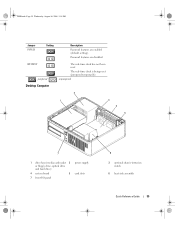
RTCRST
jumpered
Desktop Computer
The real-time clock has not been reset. The real-time clock is being reset (jumpered temporarily).
unjumpered
2
1
3
4
5
7
1 drive bays (media card reader 2 or floppy drive, optical drive and hard drive)
4 system board
5
7 front I/O panel
power supply card slots
6
3 optional chassis-intrusion switch
6 heat sink assembly
Quick Reference Guide...
Quick Reference
Guide - Page 49
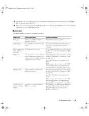
... green several A configuration error exists. See "Power Problems" in your online User's Guide.
See "Power Problems" in a power-saving mode.
Also, check Diagnostic Lights to see if ... problem was detected while the BIOS was executing. Quick Reference Guide
49 Blinking yellow
A power supply or system board failure has occurred.
System Lights
Your power light may be set incorrectly....
Quick Reference
Guide - Page 50
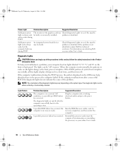
... and press the power button.
For information on the system type. Check Diagnostic Lights to see if the specific problem is in recovery mode.
The lights can...completion, and then restart the
computer.
the Run the BIOS Recovery utility, wait for a short time, and then turn off " condition, or a possible pre-BIOS failure has occurred. Diagnostic Lights
CAUTION: Before you ...
Quick Reference
Guide - Page 53
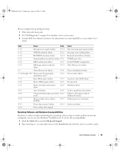
...
NVRAM read/write failure
3-2-2
1-1-4
ROM BIOS checksum failure
3-2-4
1-2-1
Programmable interval timer... Help and Support. 2 Type hardware troubleshooter in protected 4-4-2 mode
4-3-1
Memory failure above address 0FFFFh
4-4-3
4-3-3
Timer-chip counter...Interrupt vector loading failure Keyboard Controller test failure NVRAM power loss Invalid NVRAM configuration Video Memory test failure
...


