Dell Latitude E5530 Support Question
Dell Latitude E5530 Support Question
Find answers below for this question about Dell Latitude E5530.Need a Dell Latitude E5530 manual? We have 3 online manuals for this item!
Question posted by peter15231 on January 25th, 2013
The Cdrom Drive Will Not Open If I Remove Then Replace The Battery I Can Open It
The person who posted this question about this Dell product did not include a detailed explanation. Please use the "Request More Information" button to the right if more details would help you to answer this question.
Current Answers
Answer #1: Posted by prateekk007 on January 25th, 2013 2:53 PM
prateekk007

Member since:
December 5th, 2012 Points: 2,137,520

Member since:
December 5th, 2012 Points: 2,137,520
Hi peter15231
In order to remove the optical drive first you have to disconnect the battery and access panel then only you can remove it. It’s by design.
For further help you can refer to the service manual from the below mentioned link:
Please reply me if you need any further help.Thanks & Regards
Prateek K
Related Dell Latitude E5530 Manual Pages
Setup and Features Information Tech Sheet - Page 6
...the computer.
For more information regarding the configuration of your computer.
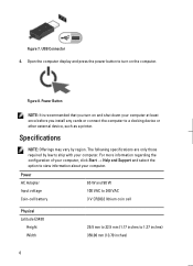
Figure 8. Figure 7. Open the computer display and press the power button to ship with your computer, click Start &#...USB Connector 4. Power AC Adapter Input voltage Coin-cell battery
65 W and 90 W 100 VAC to 240 VAC 3 V CR2032 lithium coin cell
Physical Latitude E5430
Height Width
29.9 mm to 32.5 mm ...
Statement of Volatility - Page 2
... DELL logo, Dell Precision™, OptiPlex™, Latitude™, PowerEdge™, PowerVault™, PowerConnect™,....
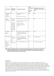
CDROM/RW/ DVD/ DVD+RW/ Diskette Drives
User replaceable
Volatile memory in GB.
AMD® is removed from...LOM Serial U18 Flash Memory
Hard drive(s)
User replaceable - Secondary power loss (removing the on-board coin-cell battery) destroys system data on the ...
User Manual - Page 2
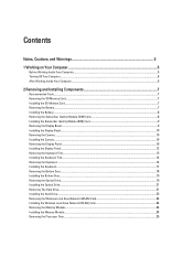
......5
Before Working Inside Your Computer...5 Turning Off Your Computer...6 After Working Inside Your Computer...6
2 Removing and Installing Components 7
Recommended Tools...7 Removing the SD Memory Card...7 Installing the SD Memory Card...7 Removing the Battery...7 Installing the Battery...8 Removing the Subscriber Identity Module (SIM) Card 8 Installing the Subscriber Identity Module (SIM) Card...
User Manual - Page 6
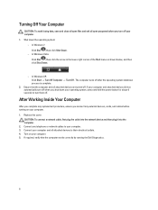
...; Turn Off Computer → Turn Off . If required, verify that the computer and all open programs before turning on your computer. 1. Shut down your operating system, press and hold the .... 3. Turn on your computer. 5. After Working Inside Your Computer
After you complete any replacement procedure, ensure you turn them off. Ensure that the computer works correctly by running the...
User Manual - Page 7

... your computer. Follow the procedures in Before Working Inside Your Computer. 2. Press in on how to release it clicks into the unlock position.
7
Removing the Battery
1.
Slide the battery release latches into place. 2. Follow the procedures in After Working Inside Your Computer. Recommended Tools
The procedures in Before Working Inside Your Computer. 2. Installing...
User Manual - Page 8

Figure 2.
Follow the procedures in Before Working Inside Your Computer. 2. Removing the Subscriber Identity Module (SIM) Card
1. Press and release the SIM card located on the battery wall. 8 Remove the battery from the computer.
Remove the battery. 3. Installing the Battery
1.
Slide the battery into its slot until it clicks into place. 2. Figure 1. 3. Follow the procedures in ...
User Manual - Page 9

... display bezel from the computer. 4. Insert the subscriber identity module (SIM) card into the slot. 2. Remove the battery. 3.
Pry up the bottom edge of the display bezel. . Installing the Subscriber Identity Module (SIM) Card
1.
Removing the Display Bezel
1. Figure 3. 5. Work your way around the sides and top edge of the display bezel. 4.
Follow...
User Manual - Page 10

... screw that secures the camera and microphone module. 5.
Follow the procedures in After Working Inside Your Computer. Installing the Display Bezel
1.
Connect the camera cable. 4. Remove:
a) battery b) display bezel 3. Installing the Camera
1. Place the camera and microphone module in position on the display bezel and work around the entire bezel until it...
User Manual - Page 13

Follow the procedures in After Working Inside Your Computer. Removing the Keyboard Trim
1. Remove the screws at the back of the keyboard trim. 6. Follow the procedures in Before Working Inside Your Computer. 2.
Remove the battery. 3. 8. Pry up the keyboard trim starting from the computer.
13 Work your way around the sides and the top edge...
User Manual - Page 14

... Working Inside Your Computer. 2. Align the keyboard trim to its compartment. 2. Removing the Keyboard
1. Press along the sides of the computer.
14 Install the battery. 4.
Installing the Keyboard Trim
1. Follow the procedures in After Working Inside Your Computer. Remove:
a) battery b) keyboard trim 3. Remove the screw at the back of the keyboard trim until it snaps...
User Manual - Page 18

... screws that all the snaps are fully engaged with the computer.
6. Removing the Bottom Door
1. Remove the battery. 3.
Press down on the keyboard to the palm rest. 7. Follow the procedures in After Working Inside Your Computer.
Figure 14.... and right side ensuring that secure the bottom door. Slide and then lift the bottom door upwards and remove it from the computer.
18 5.
User Manual - Page 19

Install the battery. 4. Remove:
a) battery b) bottom door 3. Figure 15. Removing the Optical Drive
1. Remove the screw that secure the bottom door to the computer. 3. Install the screws that secures the optical drive.
19 Follow the procedures in Before Working Inside Your Computer. 2.
Follow the procedures in After Working Inside Your Computer. Slide the bottom door into its ...
User Manual - Page 21

...to the optical drive. 2. Remove the optical drive bezel. Insert the optical drive into the computer. 5. Install :
a) bottom door b) battery 7. Remove:
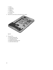
21 Figure 18. 6. Install the optical drive bracket. 3. Remove the screws that secures the optical drive in place. 6. Installing the Optical Drive
1. Engage the optical drive bezel tabs to attach the optical drive bezel to separate...
User Manual - Page 22

Use the tab to pull the hard drive bracket and release the hard drive from the computer.
22 Remove the screws that secure the hard drive bracket in place. Remove the hard drive from its connector. Figure 20. 5.
Figure 19. 4.
a) battery b) bottom door 3.
User Manual - Page 23
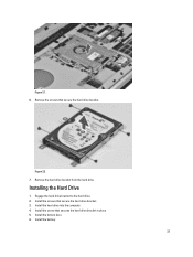
...place. 5.
Figure 22. 7. Engage the hard drive bracket to the hard drive. 2. Install the screw that secure the hard drive bracket. Install the bottom door. 6. Remove the hard drive bracket from the hard drive. Install the hard drive into the computer. 4. Figure 21. 6. Install the screws that secure the hard drive bracket. 3.
Installing the Hard Drive
1. Install the battery.
23
User Manual - Page 24
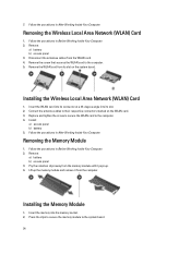
...Computer. 2. Installing the Wireless Local Area Network (WLAN) Card
1. Replace and tighten the screw to secure the WLAN card to the system ... into its connector at a 45-degree angle into the memory socket. 2. Install:
a) access panel b) battery 5. Remove:
a) battery b) access panel 3. Follow the procedures in Before Working Inside Your Computer. 2. Disconnect the antennae cables from...
User Manual - Page 25
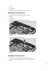
Follow the procedures in its location at the bottom of the computer. 3. Remove:
a) battery b) bottom door 3. Remove the processor door from the computer.
Place the processor door in After Working Inside Your Computer. Install: a) access panel b) battery
4. Follow the procedures in place.
Install the screws that secure the processor door in Before Working Inside Your...
User Manual - Page 28
Disconnect the :
a) LED board flat flex cable b) media button flat flex cable c) touchpad flat flex cable d) fingerprint scanner flat flex cable e) power button flat flex cable
28 Figure 27. 4. Remove the screws that secure the bottom of the computer. b) battery c) bottom door d) keyboard trim e) keyboard f) optical drive g) processor door h) hard drive 3.
User Manual - Page 30
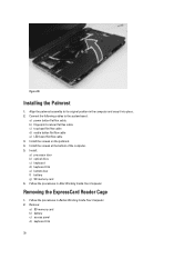
... on the palmrest. 4.
Remove:
a) SD memory card b) battery c) access panel d) keyboard trim
30 Installing the Palmrest
1. b) fingerprint scanner flat flex cable c) touchpad flat flex cable d) media button flat flex cable e) LED board flat flex cable 3. Figure 30. Follow the procedures in After Working Inside Your Computer. Install : a) processor door b) optical drive c) keyboard...
User Manual - Page 32
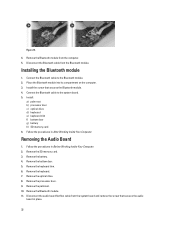
...the audio
board in place.
32 Installing the Bluetooth module
1. Remove the keyboard. 7. Removing the Audio Board
1. Remove the battery. 4. Disconnect the audio board flat flex cable from the computer. 5. Remove the optical drive. 8. Figure 31.
4. Remove the processor door. 9. Remove the Bluetooth module from the system board and remove the screw that secures the Bluetooth module...
Similar Questions

How To Make The Hard Drive Removable On A Dell E5530
(Posted by beDave 9 years ago)


How To Remove Memory From Dell Laptop Latitude E6430
(Posted by kjcGBor 10 years ago)


I Cannot Find Any Latch To Remove The Battery , How Can
I remove the battery of this xps 14 laptop
I remove the battery of this xps 14 laptop
(Posted by Kinasinger 10 years ago)