Dell ALIENWARE AURORA Support Question
Dell ALIENWARE AURORA Support Question
Find answers below for this question about Dell ALIENWARE AURORA - GAMING MACHINE - ALIENWARE AURORA.Need a Dell ALIENWARE AURORA manual? We have 2 online manuals for this item!
Question posted by jsneniri on January 11th, 2014
How To Remove Alienware Aurora Alx Bottom Side Panel
The person who posted this question about this Dell product did not include a detailed explanation. Please use the "Request More Information" button to the right if more details would help you to answer this question.
Current Answers
Related Dell ALIENWARE AURORA Manual Pages
Manual - Page 18

... CHAPTER 2: GETTING TO KNOW YOUR DESKTOP This light automatically turns off , as the light is turned off after a few seconds. In Alienware Aurora ALX, the back light will function only when the computer is turned on the light to turn on . Back Light Button
Press the back light button to view the back panel connectors.
Manual - Page 38

To remove the side panel:
1. NOTE: Theater lighting (available only on Alienware Aurora ALX) turns on page 36. Place the side panel in "Before You Begin" on automatically when the side panel is powered by internal batteries.
Slide the latch to the right to open the side panel. 4.
To replace the side panel, push the side panel against the side of...
Service Manual - Page 3
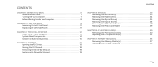
CONTENTS
CHAPTER 1: BEFORE YOU BEGIN 6 Recommended Tools 7 Turning Off Your Computer 7 Before Working Inside Your Computer 8
CHAPTER 2: LEFT SIDE-PANEL 9 Removing the Left Side-Panel 11 Replacing the Left Side-Panel 11
CHAPTER 3: TECHNICAL OVERVIEW 12 Inside View of Your Computer 13 System Board Components 14 Master I/O Board Components 15
CHAPTER 4: SHROUDS 16 Opening the...
Service Manual - Page 4
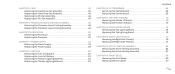
... Master I/O Board 73
CHAPTER 15: TOP LIGHTING-BOARD 74 Removing the Top Lighting-Board 76 Replacing the Top Lighting-Board 76
CHAPTER 16: RIGHT SIDE-PANEL(S 77 Removing the Right Side-Panel(s 79 Replacing the Right Side-Panel(s 81
CHAPTER 17: ACTIVE-VENTING ASSEMBLY 82 Removing the Active-Venting Assembly 84 Replacing the Active-Venting Assembly...
Service Manual - Page 11

... in Alienware Aurora ALX) turns on automatically when the left side-panel with the slots on page 6. Follow the instructions in "Before You Begin" on the side of the
computer and push the panel in a secure location. Align the tabs on page 6. 2. Slide the latch to open the left-side panel. 4. Replacing the Left Side-Panel
1. Removing the...
Service Manual - Page 18
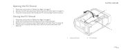
...the PCI shroud away from the chassis. Closing the PCI Shroud
1. Replace the left side-panel (see "Replacing the Left Side-Panel" on .
1 release button
2 PCI shroud
CHAPTER 4: SHROUDS
1
2 018 /018
Follow... outlets and then turn
them on page 11). 4. Remove the left side-panel (see "Removing the Left Side-Panel" on page 11). 3. Lower the PCI shroud into the chassis until it clicks...
Service Manual - Page 19

... (2)
CHAPTER 4: SHROUDS
2
2 drive-bay shroud 019 /019 Connect the drive-bay shroud battery cable to electrical outlets and then turn
them on page 6. 2. Remove the left side-panel (see "Opening the PCI Shroud" on the
master I /O board. 3. Slide the drive-bay shroud toward the front of the
chassis. 5. Close the PCI shroud...
Service Manual - Page 22
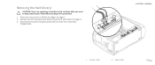
Follow the instructions in "Before You Begin" on page 11). 3. Removing the Hard Drive(s)
CAUTION: If you are replacing a hard drive that contains data you want to keep, back up... the power and data cables from the hard-drive assembly
(if applicable).
2 1
CHAPTER 5: DRIVE(S)
1 power cable
2 data cable
022 /022 Remove the left side-panel (see "Removing the Left Side-Panel" on page 6. 2.
Service Manual - Page 25

... tab and slide the optical drive out through the front of your computer to lower the drive panel.
3. Open the PCI shroud (see "Removing the Left Side-Panel" on page 6.
2.
Removing the Optical Drive(s) 3
1. Remove the left side-panel (see "Opening the PCI Shroud" on the front of the
1
computer. Follow the instructions in "Before You...
Service Manual - Page 27

CHAPTER 5: DRIVE(S)
3
1 FlexBay USB cable 3 FlexBay dock
2 securing tab
027 /027 Remove the left side-panel (see "Opening the PCI Shroud" on page 18).
5. Disconnect the FlexBay USB cable from the connector on page 6.
2. Lift the securing tab and slide the ...
Service Manual - Page 37

Follow the instructions in "Before You Begin" on page 11). 3. Remove the left side-panel (see "Removing the Left Side-Panel" on page 6. 2. WARNING: The memory module(s) may become very hot during normal operation.
Spread apart the securing clips at both ends of the memory-module ...
Service Manual - Page 44

...-bay shroud (see "Removing the Left Side-Panel" on page 6. 2. Press the tabs and lift the PCI-fan assembly out of the chassis. CHAPTER 8: ..."Before You Begin" on page 11). 3. Remove the left side-panel (see "Removing the Drive-Bay Shroud" on the master
I/O board. 7. Open the PCI shroud (see "Removing the PCI-Express
Card(s)" on page 18). 4. Remove full-length PCI-Express cards, if any (...
Service Manual - Page 48
... and CPU PUMP) on page 6.
5
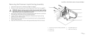
2. Ensure that secure the processor liquid-cooling assembly to the chassis rear wall.
6. Remove the four screws that it has had sufficient time to the system board.
5. CHAPTER 9: PROCESSOR LIQUID-COOLING ASSEMBLY
1 2 ... liquid-cooling assembly to cool before you touch it.
3.
Remove the left side-panel (see "Removing the Left Side-Panel" on page 11).
Service Manual - Page 52

...
CHAPTER 10: PROCESSOR
1 2 3 4
2 processor 4 release lever
052 /052 Press and push the release lever down and out and release it from the socket.
6. Remove the left side-panel (see "Removing the Processor Liquid-Cooling Assembly" on page 11). Leave the release lever extended in the socket.
5. WARNING: Despite having a plastic shield, the processor...
Service Manual - Page 57
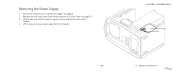
Lift the power-supply cover away from the chassis. Removing the Power Supply
1. CHAPTER 11: POWER SUPPLY
2 1
1 tab
2 power-supply cover
057 /057 Remove the left side-panel (see "Removing the Left Side-Panel" on page 6. 2. Follow the instructions in "Before You Begin" on page 11). 3. Lift the tab and slide the power-supply cover towards the back of the
chassis. 4.
Service Manual - Page 62
...Remove the left side-panel (see "Removing the Left Side-Panel" on page 6.
3. Follow the instructions in system setup (see "Opening the PCI Shroud" on the system board.
7. Remove any PCI-Express cards (see "System Board Components" on page 32).
6. Locate the battery socket (see "Removing... with a blunt object, be careful not to remove the battery.
1 1 battery release lever
CHAPTER 12...
Service Manual - Page 64
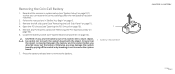
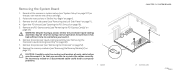
... drive-bay shroud over.
6. Remove the left side-panel (see "Removing the Left Side-Panel" on page 6.
2. Open the theater-lighting battery compartment door.
1
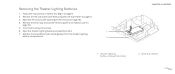
7. Removing the Theater-Lighting Batteries
1. Follow the instructions in "Before You Begin" on page 11).
3. Remove the drive-bay shroud (see "Opening the PCI Shroud" on page 19).
5. Remove the two batteries (AA...
Service Manual - Page 68
...-cooling assembly may be very hot during normal operation.
An incorrectly routed or a disconnected cable could lead to re-route the cables correctly. Remove the left side-panel (see "Removing the Processor Liquid-Cooling Assembly" on page 107) so that you disconnect it .
6. Ensure that it has had sufficient time to cool before...
Service Manual - Page 72

... on page 11). 3. Note
the routing of the chassis.
1 screws (4)
CHAPTER 14: MASTER I /O Board
1. Open the PCI shroud (see "Removing the Left Side-Panel" on the master I /O board to the chassis. 8. Remove the PCI-fan assembly (see "Removing the Drive-Bay Shroud" on page 6. 2. Follow the instructions in "Before You Begin" on
page 19...
Service Manual - Page 84

...-bay shroud (see "Removing the Left Side-Panel" on
page 19). 5. Remove the screw that secures the right top-panel to the chassis.
1 screw
CHAPTER 17: ACTIVE-VENTING ASSEMBLY
1
084 /084 Remove the left side-panel (see "Removing the Drive-Bay Shroud" on page 11). 3. Follow the instructions in Alienware Aurora ALX. 1. Removing the Active-Venting Assembly
NOTE: Active-venting assembly...
Similar Questions

How Do I Remove The Hard Drive From A Dell Inspiron D11m001 Desktop Computer
(Posted by QWEEallenx 9 years ago)

How To Open The Front Panel On The Alienware Aurora Computer
(Posted by taggbr 10 years ago)

Does Alienware Aurora Alx Runs Sata 3 ?
(Posted by carlomv 10 years ago)

Alienware Aurora R3 Desktop How To Remove Side Panel
(Posted by handgggeee 10 years ago)