Biostar MCP6P-M2 Support Question
Biostar MCP6P-M2 Support Question
Find answers below for this question about Biostar MCP6P-M2.Need a Biostar MCP6P-M2 manual? We have 1 online manual for this item!
Question posted by philroy5549 on June 5th, 2012
Sound Cable To Hard Drive
moved my desktop cable from motherboard to hard drive came loose,they are marked and color coded but don't know how the fit on hardrive...they are still in the motherboard...
Current Answers
Answer #1: Posted by TATSU on June 10th, 2012 1:07 AM
TATSU
Member since:
March 30th, 2012 Points: 186,740

Member since:
March 30th, 2012 Points: 186,740
Hello,
> I supposed U have HDD connected with IDE port ( PATA ) 'cause SATA can't be connected wrong<
it's simple the middle connector on the cable is master and the 1 on the end is slave.
If U have the HDD and/or Optical mechanic switched as cable select the connection is opposite.
The IDE or PATA connector is also keyed.
Related Biostar MCP6P-M2 Manual Pages
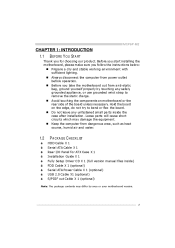
Setup Manual - Page 1

... contents here and s pecially disclaims any implied warranties of this user's manual is not allowed without first obtaining the vendor's approval in a particular ins tallation. MCP6P-M2 Setup Manual
FCC Information and Copyright
This equipment has been tes ted and found in this user's manual. The content of merchantability or...
Setup Manual - Page 3
...Loose parts will cause short circuits which may differ by touching any unfastene d small parts inside ) FDD Cable X 1 (optional) Se rial ATA Powe r Cable X 1 (optional) USB 2.0 Cable X1 (optional) S/PDIF out Cable...Cable X 1 Se rial ATA Cable X 1 Rear I/O Panel for choosing our product. Avoid touching the compone nts on the edge , do not try to remove the static charge. MCP6P-M2...tup Drive ...
Setup Manual - Page 4
... t Con trol in Connector
Slots On Board Connector
4 Motherboard Manual
1.3
MOT HERBOARD FEAT URES
SPEC Socket AM2 AMD ...cards Supports PCI-E x16 expansion cards Each connector supports 2 Floppy drives Each connector supports 1 Prin ter port Each connector supports 2 ...II
Integrated Serial ATA Con troller
LAN
Realtek RTL 8201CL
Sound
ALC662 PCI slot PCI Express x16 slot Floppy connector Prin ...
Setup Manual - Page 5
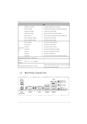
... to PS/2 Mou se Connect to D-SUB mon itor Provide RS-232 Serial connection Connect to RJ-45 ethernet cable Connect to add or remove support for any OS With or without notice. MCP6P-M2
SPEC S/PDIF ou t conn ector CPU Fan header System Fan header CMOS clear header USB conn ector Power...
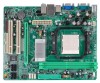
Setup Manual - Page 6
Motherboard Manual
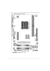
1.5
JKBMS1
MOT HERBOARD LAYOUT
JCFA N1 JATXP WR4 JKBM SPWR1
DIMMA1
J US BPWR1
JUSB1
JATXP WR1 JUSBLAN1
JUSBPW R2 IDE1
BIOS
JA UDIO1
nForce 6100-430
JCDIN1 JA UDIOF 1
DIMMB1
J US B3 JUSB2 J US B4 J CMOS1 SATA 3
Super I/O
JCOM1
Socket
VGA
A M2
L AN
PCI-EX16
BAT1
PCI1
SATA4
Codec J SPDIF_O UT1 J PRNT1
PCI2
FDD1
SATA1 JSFAN1
SATA2 JPANEL1
Not e:
Setup Manual - Page 7
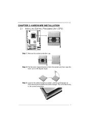
... and then raise the lever up to a 90-degree angle. The CPU will fit only in the correct orientation.
7
Step 3: Look for the white triangle on socket, and the gold triangle on CPU should point towards this white triangle. MCP6P-M2
CHAPTER 2: HARDWARE INSTALLATION 2.1 INST ALLING CENT RAL PROCESSING UNIT (CPU)
Step 1: Remove...
Setup Manual - Page 8
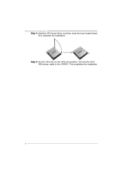
Motherboard Manual Step 4: Hold the CPU down firmly, and then close the lever toward direct B to the JCFAN1. This completes the installation.
8 Connect the CPU FAN power cable to complete the installation.
Step 5: Put the CPU Fan on the CPU and buckle it.
Setup Manual - Page 9
MCP6P-M2
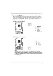
2.2
FAN HEADERS
These fan headers support cooling-fans built in the computer. The J SFAN1 supports 3-pin head connector. JCFAN1: CPU Fan Heade r... and the blac k wire is Ground and s hould be different according to the fan manufacturer. The fan cable and connector may be c onnected to pin#1. Connect the fan cable to the connector while matching the black wire to GND.
9
Setup Manual - Page 11
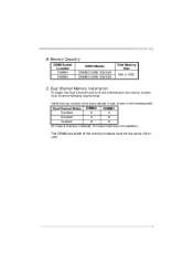
Dual Channel Memory installation
To trigger the Dual Channel f unction of the motherboard, the memory module must meet the following requirements: Install memory module of the memory module must be the same (x8 or x16)
11 ...ollowing table. C. Memory Capacity
DIMM Socket Location DIMMA1 DIMMB1 DDR2 Module 256MB/512MB/1GB/2GB 256MB/512MB/1GB/2GB Total Memory Size Max is 4GB. MCP6P-M2
B.
Setup Manual - Page 12
... Disk Conne ctor
2 1
34 33
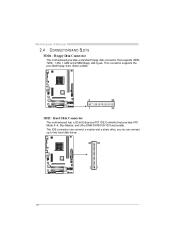
IDE1: Hard Disk Conne ctor
The motherboard has a 32-bit Enhanced PCI IDE Controller that supports 360K, 720K, 1.2M, 1.44M and 2.88M floppy disk ty pes. This connector supports the prov ided f loppy drive ribbon cables. Motherboard Manual
2.4
CONNECT ORS AND SLOT S
The motherboard prov ides a standard floppy disk connector that...
Setup Manual - Page 13
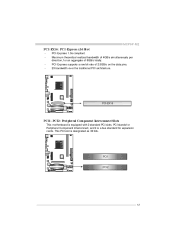
...: Pe riphe ral Component Interconne ct Slots
This motherboard is a bus standard for expansion cards. PCI1
PCI2
13 Maximum theoretical realized bandwidth of 4GB/s simultaneously per direction, f or an aggregate of 2.5GB/s on the data pins. 2X bandwidth ov er the traditional PCI architecture. MCP6P-M2
PCI-EX16: PCI-Express x16 Slot
PCI...
Setup Manual - Page 14
...2 3 4 5 6 7 8
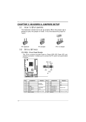
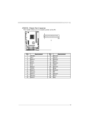
Assignment +5V N/A N/A Speaker HDD LED (+) HDD LED (-) Ground Reset control
Functio n Speaker Connector Hard drive LED Reset button
Pin 9 10 11 12 13 14 15 16
Assignment N/A N/A N/A Power LED (+) Power LED (+) Power LED (-) ... Power-on, Reset, HDD LED, Power LED, and speaker connection. Motherboard Manual
CHAPTER 3: HEADERS & JUMPERS SETUP 3.1 HOW T O SET UP JUMPERS
The illustration ...
Setup Manual - Page 15
MCP6P-M2
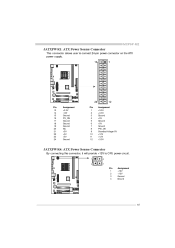
JATXPWR1: ATX Powe r Source Conne ctor
This connector allows user to connect 24-pin power connector on the ATX power supply.
13 1
24
Pin 13 ...
Setup Manual - Page 16
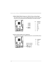
... +5V (fused) +5V (fused) USBUSBUSB+ USB+ Ground Ground Key NC
JUSB3 JUSB2 JUSB4
2 1 10 9
1 2 3 4 5 6 7 8 9 10
SATA1~SATA4: Se rial ATA Connectors
The motherboard has a PCI to connect additional USB cable on the PC f ront panel, and also can be connected with 4 channels SATA interf ace. SATA3 SATA4 SATA1 SATA2
1 4 7
Pin 1 2 3 4 5 6 7
Assignment Ground...
Setup Manual - Page 17
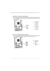
... output cable with the PC f ront panel. This header allows only HD audio front panel connector;
Pin 1
1 4
2 3 4
Assignment Left Channel Input Ground Ground Right Channel Input
17 MCP6P-M2
JAUDIO ...F1: Front Panel Audio Heade r
This header allows user to connect the audio source f rom the v ariaty dev ices, like CD-ROM, DVD-ROM, PCI sound card, PCI TV...
Setup Manual - Page 19
MCP6P-M2
JPRNT1: Printe r Port Connector
This header allows you to connector printer on the PC.
2 1 25
Pin 1 2 3 4 5 6 7 8 9 10 11 12 13
Assignment -Strobe -ALF Data 0 -Error Data 1 -Init Data 2 -Scltin Data 3 Ground Data 4 Ground Data 5
Pin 14 15 16 17 18 19 20 21 22 23 24 25 26
Assignment Ground Data 6 Ground Data 7 Ground -ACK Ground Busy Ground PE Ground SCLT Key
19
Setup Manual - Page 21
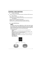
...RAID set based on the platf orm. Depending on the system environment. If any drive in a RAID 0 array system. Drawbacks: Does not deliver any env ironment ... stripes" data across multiple drives in RAID 0 and RAID 1. RAID 1: RAID 1 defines techniques for many applications. This technique reduces overall disk access time and offers high bandwidth. MCP6P-M2
CHAPTER 4: RAID FUNCTIONS 4.1...
Setup Manual - Page 23
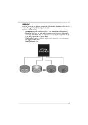
... twice the available disk space f or data redundancy, the same as RAID level 1. MCP6P-M2
RAID 0+1:
RAID 0 drives can be simultaneously used with other RAID lev els in a RAID 0+1 solution for improved performance plus resiliency. Features and Benefits
Drives: Minimum 4, and maximum is 6 or 8, depending on the platform. Benefits: Optimizes for both...
Setup Manual - Page 25
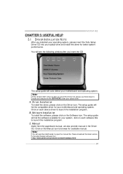
...available for your motherboard and operating system.
Pleas e download the latest version of Acrobat Reader software from the paperback manual, we also provide manual in the Driver CD. MCP6P-M2
CHAPTER 5: USEFUL... each device driver to locate and execute the file SETUP.EXE under your optical drive and install the driver for available manual. Click on the Driver icon. Driver ...
Setup Manual - Page 27
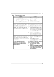
... Failure." Cannot boot system after installing 1.
on , power indicator lights are on . 3. Check cable running from hard disk 2. Screen message says "Invalid Rev iew system's equipment. MCP6P-M2
5.4
1. System inoperativ e. System does not boot from hard disk 1. Ref ormat the hard driv e. All hard disks are capable of are lit, the DIMM, press down at all securely...
Similar Questions


Two Hdd's Not Recognised
I have MCP6P3 mother Board with AMD Processor. I am unable to use two HDD's on my PC. I have one HDD...
I have MCP6P3 mother Board with AMD Processor. I am unable to use two HDD's on my PC. I have one HDD...
(Posted by shashidhar21 9 years ago)

How Do I Add A Second Hard Drive To My E System El 401 As Connected One Up But D
i tried installing one sata 500gb hard drive but wont find it.
i tried installing one sata 500gb hard drive but wont find it.
(Posted by babyboy1977 10 years ago)

Mcp6p M2+ Ver 6.1
hi, can help me? my mother board is mcp6p m2+ ver 6.1, if i turn the power switch it turn on for t...
hi, can help me? my mother board is mcp6p m2+ ver 6.1, if i turn the power switch it turn on for t...
(Posted by Anonymous-79078 11 years ago)