Biostar G41-M7 Support Question
Biostar G41-M7 Support Question
Find answers below for this question about Biostar G41-M7.Need a Biostar G41-M7 manual? We have 3 online manuals for this item!
Question posted by samirsroyroy on September 26th, 2012
In Bios Voltage Configaration..
The person who posted this question about this Biostar product did not include a detailed explanation. Please use the "Request More Information" button to the right if more details would help you to answer this question.
Current Answers
Related Biostar G41-M7 Manual Pages
Manual - Page 2
... to the hard disk drives and video monitors can do without accessing programs from a disk. BIOS activates at the first stag e o f the booting process, loading and executing the operating ... AMI BIOS Setup program on this motherboard. T he power of CMOS RAM is supplied by Microso ft, Intel and T oshiba.
1 Some additional features, such as defined in BIOS Setup.
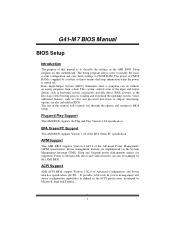
G41-M 7 BIOS Manual
BIOS Setup...
Manual - Page 3
... ensure system's compatibility and stability. Use
Load Setup Default under the Exit Menu. T he content of the motherboard. G41-M 7 BIOS Manual
PCI Bus Support
T his AMI BIOS supports the Intel CPU.
z For better system perform ance, the BIOS firmware is supported.
DRAM S upport
DDR2 SDRAM (Double Data Rate II Synchronous DRAM) is being continuously updated...
Manual - Page 12
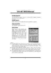
... T emperature. Advanced
BIOS S ETUP UTILITY
Hardw are Health Co nfiguration
H/W H ealth Functio n
[ Enabled]
Shutd own Temperatu re Function[ Disabled]
CPU T emperature SYSTE M Temperature
Enab les Hardware Heal th Monitorin g Devi ce. Options: Enabled (Default) / Disabled
Shutdow n Temperature Function
T his item shows the system temperature, fan speed, and voltage information. C hange...
Manual - Page 15
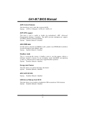
...Set this value to allow the ACPIBIOS to add a pointer to enable or disable the motherboard's APIC (Advan ced Programmable Interrupt Controller). To run in the Root System Description T able... select the version of ACPI. A headless server is a server-speci fic feature. G41-M 7 BIOS Manual
ACPI Version Features T he APIC provides multiprocessor support, more IRQs and faster interrupt...
Manual - Page 16
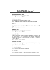
... awak ens the system from PCI card returns the system to Full ON state.
Set the Wake on LAN (WOL) jumper on motherboard to enable or disabled the HPET. G41-M 7 BIOS Manual
High Performance Event Timer T his item allows you to control the wake on ring function. Options: Enabled (Default) / Disabled
Resume On...
Manual - Page 29
G41-M 7 BIOS Manual
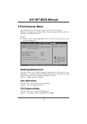
6 Performance Menu
T his submenu allows you to change voltage and clock of this menu may damage the device.)
Notice
z Beware of ...Intel (R) SpeedStep (tm) tech Ratio CMOS Setting CPU F requency Sett ing PCIE Clock By PCIE Frequency Set ting DRAM Frequency
> ALL Voltage Conf iguration
Confi gure DRAM Tim ing by SPD
[Enabled] [ x15.0] [200] [Auto] [100] [Auto]
[Enabled]
S...
Manual - Page 30
G41-M 7 BIOS Manual
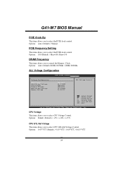
PCIE Clock By
T his item allows you to select the PCIE clock control Options: Auto (Default) / Manual
PCIE Frequency Setting
T his item allows you to select CPU Voltage Control. Options: 0.67*VTT (Default) / 0.65*VTT / 0.63*VT T / 0.615*VTT
29 Options: Auto (Default) /DDR2 667Mhz / DDR2 800Mhz
ALL Voltage Configuration
Volta ge...
Manual - Page 31
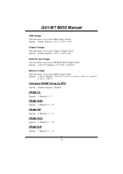
Options: 0.63*VTT (Default) / 0.61*VTT / 0.60*VT T
Memory Voltage T his item allows you to select FSB Voltage Control. G41-M 7 BIOS Manual
FSB Voltage T his item allows you to select DDR Voltage Control. Options: 1.950 V (Default) / 2.055 V / 2.153 V / 2.250 V / 2.557 V / 2.649 V /
2.742 V / 2.837 V
Configure DRAM Timing by SP D
Options: Enabled (Default) / Disabled
DRAM tCL
Options: 3 (...
Setup Manual - Page 1
... their respective companies.
All the brand and product names are designed to the contents here without notice and we will not occur in a particular installation.
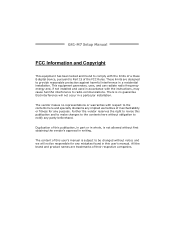
G41-M7 Setup Manual
FCC Information and Copyright
This equipment has been tested and found in this user's manual. The content of this publication and to make...
Setup Manual - Page 3
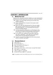
CHAPTER 1: INTRODUCTION
G41-M7
1.1 BEFORE YOU START
Thank you take the motherboard out from anti-static bag, ground yourself properly by touching any unfastened small parts ... Do not leave any safely grounded appliance, or use grounded wrist strap to area or your motherboard version.
1 Loose parts will cause short circuits which may be different due to remove the static charge.
...
Setup Manual - Page 5
The input / output function of each audio jack listed above represents the default setting. G41-M7
SPEC
Front Panel Connector
x1 Supports front panel facilities
Front Audio Connector
x1 Supports front panel audio function
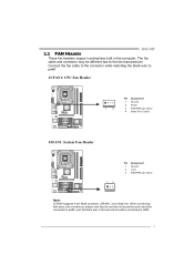
CPU Fan Header
x1 CPU Fan power ...
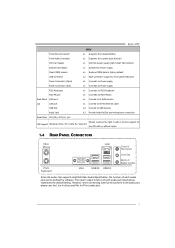
Setup Manual - Page 7
G41-M7
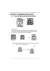
CHAPTER 2: HARDWARE INSTALLATION 2.1 INSTALLING CENTRAL PROCESSING UNIT (CPU)
Special Notice: Remove Pin Cap before installation, and make good preservation for future use.
Pin-Cap Step 1: ...
Setup Manual - Page 9
... the red wire is the positive and should be connected to pin#2, and the black wire is Ground and should be different due to GND.
7 G41-M7
2.2 FAN HEADERS
These fan headers support cooling-fans built in the computer. JSFAN1, 3-pin head one. Connect the fan cable to the connector while matching...
Setup Manual - Page 13
... of 4GB/s simultaneously per
direction, for expansion cards.
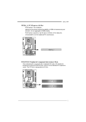
This PCI slot is equipped with 2 standard PCI slots. G41-M7 PEX16_1: PCI-Express x16 Slot - PCI1 PCI2
11 PEX16_1
PCI1/PCI2: Peripheral Component Interconnect Slots
This motherboard is designated as 32 bits. PCI-Express 1.0a compliant. - PCI stands for Peripheral Component Interconnect, and it...
Setup Manual - Page 15
G41-M7
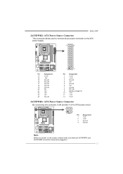
JATXPWR2: ATX Power Source Connector
This connector allows user to connect 24-pin power connector...
22
+5V
23
+5V
24
Ground
Pin Assignment
1
+3.3V
2
+3.3V
3
Ground
4
+5V
5
Ground
6
+5V
7
Ground
8
PW_OK
9
Standby Voltage+5V
10
+12V
11
+12V
12
+3.3V
JATXPWR1: ATX Power Source Connector
By connecting this connector, it will provide +12V to CPU power circuit.
4
...
Setup Manual - Page 17
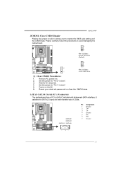
... pin2-3 allows user to "Pin 1-2 close ". 3. Set the jumper to restore the BIOS safe setting and the CMOS data. SATA1~SATA4: Serial ATA Connectors
The motherboard has a PCI to avoid damaging the motherboard.
3
1
Pin 1-2 Close: Normal Operation (Default).
3
1
3
Pin 2-3 Close:...the CMOS data.
Remove AC power line. 2. G41-M7
JCMOS1: Clear CMOS Header
Placing the jumper on the AC. 6.
Setup Manual - Page 21
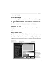
4.2 SOFTWARE
G41-M7
Installing Software
1. The drivers installation program would like to send the copy to the optical drive. Before you... the system information which would be able to complete the installation. This utility will see the software icon "eHOT Line" / "BIOS Update" appears on -screen instructions to send out the mail. Provide the e-ma il addr ess that helps you fix the ...
Setup Manual - Page 23
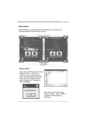
After the saving process, finish dialog will show .
Click on this button, the saving dialog will show . Choose the position to update your motherboard BIOS under Windows system. G41-M7
BIOS Update
BIOS Update is a convenient utility which allows you to save file and enter file name. (We recommend that the file name should be English/number...
Setup Manual - Page 25
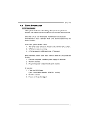
... fan is over heated, the motherboard will shutdown automatically to relief the CPU protection function.
1. Remove the power cord from power supply for seconds. 3. Clear the CMOS data. (See "Close CMOS Header: JCMOS1" section) 2. Power on system for seconds. 3. In this case, please double check: 1. G41-M7
4.3 EXTRA INFORMATION
CPU Overheated If the...
Setup Manual - Page 27
Before declaring the
motherboard beyond all other expansion
6, 7
cards are absent, consult your system manufacturer. Insert the ... be faulty.
25 If the video adapter is an add-in card, replace or
8
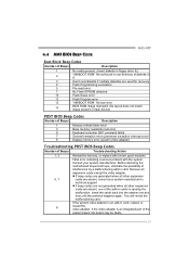
reseat the video adapter. 4.4 AMI BIOS BEEP CODE
G41-M7
Boot Block Beep Codes
Number of Beeps
Description
1
No media present. (Insert diskette in floppy drive A:)
2
"AMIBOOT.ROM"...
Similar Questions

Display Fades While Booting And Screen Becomes Dark. Motherboard P4m890-m7 Te
(Posted by shamnaarai 2 years ago)

Bio Star G 31 D M7 Jcmos Pin Setting
How i know jcmos pin nos as i forgot in my g31 d m7 ver 8.4
How i know jcmos pin nos as i forgot in my g31 d m7 ver 8.4
(Posted by yasinvora74 9 years ago)


8gb Ram On Motherboard G31 M7 V 6.5 Te
is there any way I can instal 8GB RAM on motherboard G31 M7 v 6.5 TE?
is there any way I can instal 8GB RAM on motherboard G31 M7 v 6.5 TE?
(Posted by placewithspace 10 years ago)
Cpu Quad Support
HI, is the motherboard Biostar G41-M7 will support QUAD Q8300 SLGUR?,Normally it support Q8300 QHJC...
HI, is the motherboard Biostar G41-M7 will support QUAD Q8300 SLGUR?,Normally it support Q8300 QHJC...
(Posted by julioleste 11 years ago)