Acer Aspire V3-771 Support Question
Acer Aspire V3-771 Support Question
Find answers below for this question about Acer Aspire V3-771.Need a Acer Aspire V3-771 manual? We have 1 online manual for this item!
Question posted by mrpope on November 15th, 2013
How Do I Remove Motherboard From Acer Aspire 7560-sb416
How do I remove the motherboard from this pc? I have removed every visible screw and still can not get it to come apart. Are there any hidden screws?
Current Answers
Related Acer Aspire V3-771 Manual Pages
Acer Aspire V3-771G Notebook Service Guide - Page 105
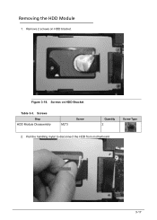
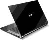
Figure 3-18. Removing the HDD Module 0 1.
Screws Step
HDD Module Disassembly
M2*3
Screw
Quantity 2
Screw Type
2. Pull the handling mylar to disconnect the HDD from motherboard.
3-17 Remove 2 screws on HDD Bracket
Table 3-3. Screws on HDD bracket.
Acer Aspire V3-771G Notebook Service Guide - Page 106
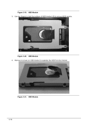
Figure 3-20. HDD Module 4.
Figure 3-21.
Use two fingers to hold the notches of HDD bracket, lift to separate the HDD from the bracket. Remove 4 screws on HDD bracket to remove HDD module. HDD Module 3. HDD Module 3-18 Figure 3-19.
Acer Aspire V3-771G Notebook Service Guide - Page 109
Remove 1 screw and ensure the cables are well clear of the Main (black) and Auxiliary (white) cables. Removing the WLAN Card 0 1. Figure 3-26. WLAN Card
3-21
WLAN Card 2. Figure 3-27. Use a pair of plastic tweezers to clamp the antenna cable connectors, disconnect 2 cables from the WLAN module.
+ IMPORTANT:
Note the connector positions of the WLAN module.
Acer Aspire V3-771G Notebook Service Guide - Page 111
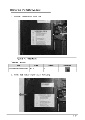
Pull the ODD module completely out of the housing. Removing the ODD Module 0 1.
Remove 1 screw from the bottom case. ODD Module
Table 3-6. Figure 3-30. Screw Type
3-23 Screws
Step ODD Module Disassembly
Screw M2*3
Quantity 1
2.
Acer Aspire V3-771G Notebook Service Guide - Page 112
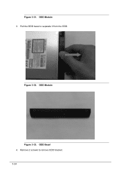
Pull the ODD bezel to remove ODD bracket. 3-24
ODD Module
Figure 3-33. Figure 3-32. Remove 2 screws to separate it from the ODD. ODD Bezel 4. Figure 3-31. ODD Module 3.
Acer Aspire V3-771G Notebook Service Guide - Page 115
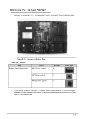
... to the gap between top case palmrest and bottom case.pry to release all latches,then lift the bottom edge of top case palmrest.
3-27 Screws
Step Bottom Case Disassembly
Screw M2.5*7 (red cycled)
M2*3 (blue cycled) M2*2 (yellow cycled)
Quantity 19
Screw Type
5 2
2. Remove 19 screws(M2.5*7) , 5 screws(M2*3) and 2 screws(M2*2)on Bottom Case
Table 3-9.
Acer Aspire V3-771G Notebook Service Guide - Page 119
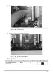
Figure 3-45. Screws
Step
Touchpad Switch Board Disassembly
Screw M2*3
Quantity 2
Screw Type
3-31 Touchpad FFC 4. Figure 3-44.
Tear off the touchpad FFC from touchpad switch board. Remove 2 screws from touchpad. 3. Touchpad Switch Board
Table 3-10.
Acer Aspire V3-771G Notebook Service Guide - Page 121
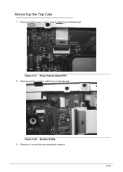
Disconnect the speaker cable from the keyboard bracket.
3-33 Speaker Cable 3. Figure 3-47. Removing the Top Case 0 1. Figure 3-48.
Remove 1 screw from motherboard. Power Switch Board FFC 2. Disconnect the power switch board cable from motherboard.
Acer Aspire V3-771G Notebook Service Guide - Page 122
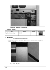
Use a plastic pry slice to insert to the gap between top case and bottom case, pry to remove this screw.
4. Screws
Step Top Case Disassembly
M2.5*5
Screw
Quantity 1
Screw Type
+ IMPORTANT:
Do not forget to release all latches.
3-34
Figure 3-50. Figure 3-49. Keyboard Bracket Screw
Table 3-11. Top Case
Acer Aspire V3-771G Notebook Service Guide - Page 126
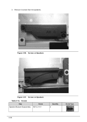
3. Screws on Speakers
Figure 3-57. Screws
Step Speaker Module Disassembly
Screw M2*2.2+5.7
Quantity 4
Screw Type
3-38 Screws on Speakers
Table 3-12. Remove 4 screws from the speakers. Figure 3-56.
Acer Aspire V3-771G Notebook Service Guide - Page 128
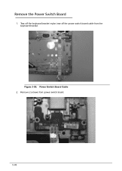
Tear off the keyboard bracket mylar, tear off the power switch board cable from power switch board.
3-40
Figure 3-59. Remove 2 screws from the keyboard bracket. Power Switch Board Cable 2. Remove the Power Switch Board 0 1.
Acer Aspire V3-771G Notebook Service Guide - Page 130
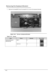
Figure 3-62. Screws
Step
Keyboard Bracket Disassembly
Screw M2*3
Quantity 6
M1.6*2.5
9
Screw Type
3-42 Screws on Keyboard Bracket
Table 3-14. Remove 6 screws(M2*3) and 9 screws(M1.6*2.5) from the keyboard bracket.
Removing the Keyboard Bracket 0 1.
Acer Aspire V3-771G Notebook Service Guide - Page 135
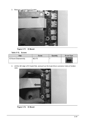
Figure 3-72. IO Board
3-47 Remove 1 screw from connector holes of IO board first, and pull out the board from IO board. Screws
Step IO Board Disassembly
Screw M2.5*5
Quantity 1
Screw Type
4. IO Board
Table 3-15. Figure 3-71.
3. Lift the left edge of bottom case.
Acer Aspire V3-771G Notebook Service Guide - Page 138
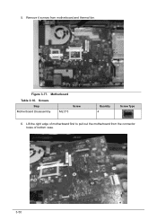
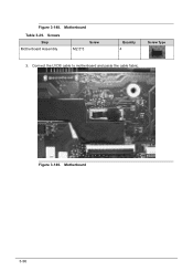
5. Motherboard
Table 3-16. Lift the right edge of motherboard first to pull out the motherboard from motherboard and thermal fan. Remove 4 screws from the connector holes of bottom case.
3-50 Screws
Step Motherboard Disassembly
M2.5*5
Screw
Quantity 4
Screw Type
6. Figure 3-77.
Acer Aspire V3-771G Notebook Service Guide - Page 140
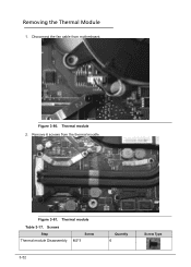
Figure 3-80. Screws Step
Thermal module Disassembly
Screw M2*3
3-52
Quantity 6
Screw Type Removing the Thermal Module 0 1.
Thermal module
Table 3-17. Figure 3-81. Thermal module 2. Remove 6 screws from motherboard. Disconnect the fan cable from the thermal moudle.
Acer Aspire V3-771G Notebook Service Guide - Page 146
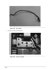
Remove 4 screws from the hinges. Screws on Hinges 3-58 Figure 3-89. Figure 3-88. DC-in Cable 3.
Acer Aspire V3-771G Notebook Service Guide - Page 150
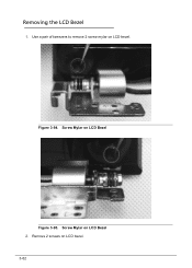
Screw Mylar on LCD Bezel
Figure 3-95. Figure 3-94. Screw Mylar on LCD Bezel 2. Removing the LCD Bezel 0 1. Use a pair of tweezers to remove 2 screw mylar on LCD bezel. 3-62 Remove 2 screws on LCD bezel.
Acer Aspire V3-771G Notebook Service Guide - Page 155
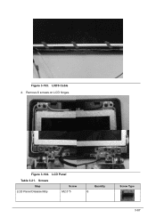
LVDS Cable 4. Remove 6 screws on LCD hinges. Screws
Step LCD Panel Disassembly
Screw M2.5*5
Quantity 6
Screw Type
3-67 LCD Panel
Table 3-21. Figure 3-103. Figure 3-104.
Acer Aspire V3-771G Notebook Service Guide - Page 157
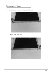
LCD Hinge
3-69 Figure 3-106. Removing the Hinges 0 1. Remove 8 screws to separate the hinges from LCD panel.
Acer Aspire V3-771G Notebook Service Guide - Page 184
Motherboard 3-96 Figure 3-149. Connect the LVDS cable to motherboard and paste the cable fabric. Figure 3-148. Screws
Step Motherboard Assembly
M2.5*5
Screw
Quantity 4
Screw Type
3.
Motherboard
Table 3-29.
Similar Questions

Current Bios For Acer Aspire V3 771-6833
what is the current bios for an acer aspire v3 771-6833?
what is the current bios for an acer aspire v3 771-6833?
(Posted by trehm 7 years ago)

How Do I Remove The Screen On Acer Aspire 7560-sb416 Laptop?
(Posted by bbcz5244 10 years ago)

How To Replace A Key On Acer Aspire 7560-sb416 Laptop
(Posted by thihlare 10 years ago)

Acer Aspire V3-771-6470 Hard Drive Crashed.
Geek squad at Best Buy can't seem to do anything for us. They want to install a new drive, so we nee...
Geek squad at Best Buy can't seem to do anything for us. They want to install a new drive, so we nee...
(Posted by lboller100448 10 years ago)

How Can I Find Bluetooth In My Acer Aspire V-3 771?
(Posted by ritvariikonen 11 years ago)