
Installation Manual
Page 1
English Integrated TV/Soundbar Pedestal Socle intégré pour téléviseur et projecteur de son YTS-T500 Printed in Malaysia WU17410-1 G Install Manual Manuel d'installation Installationsanleitung Installationsanvisningar Manuale d'installazione Manual de instalación ...and installation work , so take measures to prevent it out well before proceeding according to the owner's manual of the TV. Yamaha shall not bear any responsibility for proper ventilation, refer to their directions. 19 After reading, keep this install manual carefully prior to...
English Integrated TV/Soundbar Pedestal Socle intégré pour téléviseur et projecteur de son YTS-T500 Printed in Malaysia WU17410-1 G Install Manual Manuel d'installation Installationsanleitung Installationsanvisningar Manuale d'installazione Manual de instalación ...and installation work , so take measures to prevent it out well before proceeding according to the owner's manual of the TV. Yamaha shall not bear any responsibility for proper ventilation, refer to their directions. 19 After reading, keep this install manual carefully prior to...
Installation Manual
Page 2
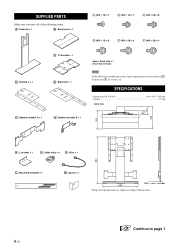
SUPPLIED PARTS Make sure you have all of the following items. : Pedestal × 1 : Base board × 1 (M5 × 16) × 7 (M5 × 16) × 7 (M5 × 20) × 8 (M6 × 16) × 8 (M6 × 20) × 4 (M8 × 20) × 4 : Bracket L × 1 : Speaker bracket A × 1 : TV bracket × 1 : Bracket R × 1 Spare: Each size × 1 (6 screws in total) Note In the following assembly procedure, these supplied parts are subject to change without notice. ☞ Continue to page 1 ii En SPECIFICATIONS • Dimensions (W × H × D 650 &#...
SUPPLIED PARTS Make sure you have all of the following items. : Pedestal × 1 : Base board × 1 (M5 × 16) × 7 (M5 × 16) × 7 (M5 × 20) × 8 (M6 × 16) × 8 (M6 × 20) × 4 (M8 × 20) × 4 : Bracket L × 1 : Speaker bracket A × 1 : TV bracket × 1 : Bracket R × 1 Spare: Each size × 1 (6 screws in total) Note In the following assembly procedure, these supplied parts are subject to change without notice. ☞ Continue to page 1 ii En SPECIFICATIONS • Dimensions (W × H × D 650 &#...

Installation Manual
Page 5
Refer to *2 in the illustration above . Note The arrows on and should be toward the top of and . Le nombre de trous que possèdent et varie selon les vis définies à l'étape 2-2-2. Reportez-vous à l'illustration ci-dessus, puis fixez et . Reportez-vous à l'illustration *2 ci-dessus. The holes for and vary depending on the TV (if X checked in step 2-2-2. Reportez-vous à l'illustration *1 ci-dessus. If and touch each other when you place them on the screw checked in step 2-2-1 is 20 cm), reverse the position of the TV. Remarque Les ...
Refer to *2 in the illustration above . Note The arrows on and should be toward the top of and . Le nombre de trous que possèdent et varie selon les vis définies à l'étape 2-2-2. Reportez-vous à l'illustration ci-dessus, puis fixez et . Reportez-vous à l'illustration *2 ci-dessus. The holes for and vary depending on the TV (if X checked in step 2-2-2. Reportez-vous à l'illustration *1 ci-dessus. If and touch each other when you place them on the screw checked in step 2-2-1 is 20 cm), reverse the position of the TV. Remarque Les ...

Installation Manual
Page 6
Refer to the number shown on is at the same height as shown in the illustration. 2 Check which number on the bar that the hole on aligns with mounting hole B, and check the number again. Si aucun numéro n'est assigné à votre haut-parleur, alignez au trou de montage B, puis vérifiez à nouveau le numéro. MEMO Number 3 Tighten (2 screws) temporarily around 5 turns into the holes at the bottom of your speaker exists, align with mounting hole A on or , as the corresponding number you checked in 2. 2-4 Vérifiez l'emplacement de montage de sur ...
Refer to the number shown on is at the same height as shown in the illustration. 2 Check which number on the bar that the hole on aligns with mounting hole B, and check the number again. Si aucun numéro n'est assigné à votre haut-parleur, alignez au trou de montage B, puis vérifiez à nouveau le numéro. MEMO Number 3 Tighten (2 screws) temporarily around 5 turns into the holes at the bottom of your speaker exists, align with mounting hole A on or , as the corresponding number you checked in 2. 2-4 Vérifiez l'emplacement de montage de sur ...
Installation Manual
Page 9
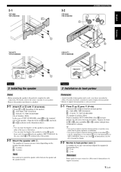
3-1 YSP-4000 YSP-5100/4100 3-2 YSP-4000 YSP-5100/4100 ASSEMBLING/MONTAGE English Français YAS-81/71 YHT-S1400/S400 YHT-S1400/S400 YAS-81/71 YHT-S1400/S400 YAS-81/71 English 3 Installing the speaker Français 3 Installation du haut-parleur Notes • Before mounting the speaker to the terminal side of the speaker. 3-2 Mount the speaker with (4 screws). y • You can adjust the height of screws you use varies depending on the speaker bracket attached. : 4 screws : 2 screws Note Be careful not to the terminal side of your speaker is attached. 3-1 Attach ...
3-1 YSP-4000 YSP-5100/4100 3-2 YSP-4000 YSP-5100/4100 ASSEMBLING/MONTAGE English Français YAS-81/71 YHT-S1400/S400 YHT-S1400/S400 YAS-81/71 YHT-S1400/S400 YAS-81/71 English 3 Installing the speaker Français 3 Installation du haut-parleur Notes • Before mounting the speaker to the terminal side of the speaker. 3-2 Mount the speaker with (4 screws). y • You can adjust the height of screws you use varies depending on the speaker bracket attached. : 4 screws : 2 screws Note Be careful not to the terminal side of your speaker is attached. 3-1 Attach ...