
Installation Manual
Page 1
... following speaker models. (As of October, 2009) YSP-4000, YSP-5100/4100, YAS-81/71, YHT-S1400/S400 i En Yamaha shall not bear any responsibility for any broken parts. 10 Do not install in a humid or dusty place, or where your TV...safety during the installation. English Integrated TV/Soundbar Pedestal Socle intégré pour téléviseur et projecteur de son YTS-T500 Printed in Malaysia WU17410-1 G Install Manual Manuel d'installation Installationsanleitung Installationsanvisningar Manuale d'installazione Manual de instalación Installatiehandleiding Français...
... following speaker models. (As of October, 2009) YSP-4000, YSP-5100/4100, YAS-81/71, YHT-S1400/S400 i En Yamaha shall not bear any responsibility for any broken parts. 10 Do not install in a humid or dusty place, or where your TV...safety during the installation. English Integrated TV/Soundbar Pedestal Socle intégré pour téléviseur et projecteur de son YTS-T500 Printed in Malaysia WU17410-1 G Install Manual Manuel d'installation Installationsanleitung Installationsanvisningar Manuale d'installazione Manual de instalación Installatiehandleiding Français...
Installation Manual
Page 2
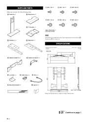
SPECIFICATIONS • Dimensions (W × H × D 650 × 867 × 398 mm • Weight ...17.0 kg Unit: mm : Speaker bracket B × 1 : L bracket × 1 : Cable clips × 4 : Wire × 1 : Mounting template × 1 : Spacer × 1 Design and specifications are described as for parts and for screws, etc. SUPPLIED PARTS Make sure you have all of the following items. : Pedestal × 1 : Base board × 1 (M5 × 16) × 7 (M5 × 16) × 7 (M5 × 20) × 8 (M6 × 16) × 8 (M6 × 20) × 4 (M8 × 20) × 4 : ...
SPECIFICATIONS • Dimensions (W × H × D 650 × 867 × 398 mm • Weight ...17.0 kg Unit: mm : Speaker bracket B × 1 : L bracket × 1 : Cable clips × 4 : Wire × 1 : Mounting template × 1 : Spacer × 1 Design and specifications are described as for parts and for screws, etc. SUPPLIED PARTS Make sure you have all of the following items. : Pedestal × 1 : Base board × 1 (M5 × 16) × 7 (M5 × 16) × 7 (M5 × 20) × 8 (M6 × 16) × 8 (M6 × 20) × 4 (M8 × 20) × 4 : ...

Installation Manual
Page 5
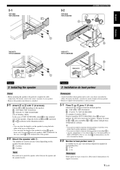
Si et se touchent lorsque vous les placez sur le téléviseur, (si la distance X mesurée à l'étape 2-2-1 est de 20 cm), inversez la position de et . Note The arrows on and should be toward the top of and . Français 2-3 Fixez et . Refer to the illustration above . Reportez-vous à l'illustration *1 ci-dessus. English Français 2-3 When using Lors de l'utilisation de *1 When using / Lors de l'utilisation de / *2 Screws checked in step 2-2-2. Le nombre de trous que possèdent et varie selon les vis définies à l'étape...
Si et se touchent lorsque vous les placez sur le téléviseur, (si la distance X mesurée à l'étape 2-2-1 est de 20 cm), inversez la position de et . Note The arrows on and should be toward the top of and . Français 2-3 Fixez et . Refer to the illustration above . Reportez-vous à l'illustration *1 ci-dessus. English Français 2-3 When using Lors de l'utilisation de *1 When using / Lors de l'utilisation de / *2 Screws checked in step 2-2-2. Le nombre de trous que possèdent et varie selon les vis définies à l'étape...

Installation Manual
Page 6
When using YSP-4100 Par ex., lors de l'utilisation de YSP-4100 English Français 2-4 Check the location to attach and the TV. 1 Place over mounting hole A on or so that corresponds to the name of your TV. MEMO Number 3 Tighten (2 screws) temporarily around 5 turns into the holes at the same height as shown in 2. 2-4 Vérifiez l'emplacement de montage de sur le téléviseur. 1 Placez sur le trou de montage A de ou de manière à aligner le trou situé sur au trou de montage A de ou , comme indiqué dans l'illustration. 2 Vérifiez quel numéro ...
When using YSP-4100 Par ex., lors de l'utilisation de YSP-4100 English Français 2-4 Check the location to attach and the TV. 1 Place over mounting hole A on or so that corresponds to the name of your TV. MEMO Number 3 Tighten (2 screws) temporarily around 5 turns into the holes at the same height as shown in 2. 2-4 Vérifiez l'emplacement de montage de sur le téléviseur. 1 Placez sur le trou de montage A de ou de manière à aligner le trou situé sur au trou de montage A de ou , comme indiqué dans l'illustration. 2 Vérifiez quel numéro ...
Installation Manual
Page 9
y • You can adjust the height of the speaker by using the holes either at the top or at the bottom. • You can adjust the height to as shown in the illustration above. Pour plus de détails, consultez le mode d'emploi du haut-parleur. • Retirez le support du haut-parleur si celui-ci est fixé. 3-1 Fixez ou avec (4 vis). Align the holes on and , and stick to set the speaker by setting upside down, only if you use and your speaker. • Remove the speaker stand when it is YHT-S1400/S400. Dans ce cas, fixez au haut-parleur, du côté o&#...
y • You can adjust the height of the speaker by using the holes either at the top or at the bottom. • You can adjust the height to as shown in the illustration above. Pour plus de détails, consultez le mode d'emploi du haut-parleur. • Retirez le support du haut-parleur si celui-ci est fixé. 3-1 Fixez ou avec (4 vis). Align the holes on and , and stick to set the speaker by setting upside down, only if you use and your speaker. • Remove the speaker stand when it is YHT-S1400/S400. Dans ce cas, fixez au haut-parleur, du côté o&#...