

Block Diagram
Page 1
...+48V-ON +48V PHANTOM MASTER LED LED LAMP PANEL LED DIMMER OUTPUT METER DIMMER LAMP DIMMER LAMP-ON 12V LAMP ON PREVIEW PREVIEW PM5000 Level Diagram +30dBu +20dBu PAD: ON (26dB) GAIN: Min. [+16dBu] +10dBu 0dBu -10dBu PAD: OFF (0dB) GAIN... PHONES OUT [100mW@8Ω] +30dBu +20dBu +10dBu 0dBu -10dBu -20dBu -30dBu -40dBu -50dBu -60dBu PM5000 Block Diagram PM5000-52C :1~48 PM5000-36 :1~32 PM5000-28 :1~24 MONO INPUT [-60~+16dBu] +48V from Phantom Master PAD HA1 HA2 0dB 26dB GAIN Trim 26dB 0dB...] CONTROL *STEREO AUX SUB IN and GROUP/AUX SUB IN are not provided on the PM5000-28.
...+48V-ON +48V PHANTOM MASTER LED LED LAMP PANEL LED DIMMER OUTPUT METER DIMMER LAMP DIMMER LAMP-ON 12V LAMP ON PREVIEW PREVIEW PM5000 Level Diagram +30dBu +20dBu PAD: ON (26dB) GAIN: Min. [+16dBu] +10dBu 0dBu -10dBu PAD: OFF (0dB) GAIN... PHONES OUT [100mW@8Ω] +30dBu +20dBu +10dBu 0dBu -10dBu -20dBu -30dBu -40dBu -50dBu -60dBu PM5000 Block Diagram PM5000-52C :1~48 PM5000-36 :1~32 PM5000-28 :1~24 MONO INPUT [-60~+16dBu] +48V from Phantom Master PAD HA1 HA2 0dB 26dB GAIN Trim 26dB 0dB...] CONTROL *STEREO AUX SUB IN and GROUP/AUX SUB IN are not provided on the PM5000-28.
Owner's Manual
Page 7
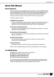
... of mono and stereo input channels. The manual is organized as described below: ■ PM5000-52C (52 input channels/center master) ■ PM5000-36 (36 input channels/right master) ■ PM5000-28 (28 input channels/right master) For each section and module are the same. The names of ...physical controls such as a whole. Since the operational design of the PM5000 is based on to describing the features and functions of the various PM5000 modules. New features and...
... of mono and stereo input channels. The manual is organized as described below: ■ PM5000-52C (52 input channels/center master) ■ PM5000-36 (36 input channels/right master) ■ PM5000-28 (28 input channels/right master) For each section and module are the same. The names of ...physical controls such as a whole. Since the operational design of the PM5000 is based on to describing the features and functions of the various PM5000 modules. New features and...

Owner's Manual
Page 8
Contents 8 Foreword 6 About This Manual 7 General Approach 7 The PM5000 Models 7 PM5000 Overview 10 Panel Layout 10 Top Panel 10 Rear Panel 12 Expansion: Connecting to External Equipment 14 Cascade 14 MIDI 14 GPI (General Purpose Interface ... Master Mute Switch Group Control 24 Master Out Section 26 Multiple Masters In Single Modules 26 Basic Signal Routing 27 Controls Common To All Masters 28 Stereo Aux Master Module 30 G/A (Group/Aux) Master Module 31 Group/Aux Switching 32 Stereo and Mono Master Modules 34 Matrix Send and Master Out...
Contents 8 Foreword 6 About This Manual 7 General Approach 7 The PM5000 Models 7 PM5000 Overview 10 Panel Layout 10 Top Panel 10 Rear Panel 12 Expansion: Connecting to External Equipment 14 Cascade 14 MIDI 14 GPI (General Purpose Interface ... Master Mute Switch Group Control 24 Master Out Section 26 Multiple Masters In Single Modules 26 Basic Signal Routing 27 Controls Common To All Masters 28 Stereo Aux Master Module 30 G/A (Group/Aux) Master Module 31 Group/Aux Switching 32 Stereo and Mono Master Modules 34 Matrix Send and Master Out...

Owner's Manual
Page 10
PM5000 Overview PM5000 Overview Panel Layout The layout of the console's input modules make up the "input channel section." For example, all other models it is made up of an "EQ block," a "fader block," and others. Top Panel PM5000-52C PM5000-28 10 NOTE In this manual the console's main ...functional groups are "modules." In the PM5000 each input channel is located to as "sections." The basic hardware divisions are referred to the...
PM5000 Overview PM5000 Overview Panel Layout The layout of the console's input modules make up the "input channel section." For example, all other models it is made up of an "EQ block," a "fader block," and others. Top Panel PM5000-52C PM5000-28 10 NOTE In this manual the console's main ...functional groups are "modules." In the PM5000 each input channel is located to as "sections." The basic hardware divisions are referred to the...

Owner's Manual
Page 12
... or a talkback cable. One of the main functions of external equipment. NOTE The two screws on the front panel. Rear Panel PM5000-52C ! ∞ ^% $ PM5000-28 ! # @ ¡º @ ! ∞ ^% $ NOTE All PM5000 inputs and outputs are concentrated in conjunction with some types of this section. A fader time function is specified via a utility...
... or a talkback cable. One of the main functions of external equipment. NOTE The two screws on the front panel. Rear Panel PM5000-52C ! ∞ ^% $ PM5000-28 ! # @ ¡º @ ! ∞ ^% $ NOTE All PM5000 inputs and outputs are concentrated in conjunction with some types of this section. A fader time function is specified via a utility...

Owner's Manual
Page 13
... for details. Please check the supplied block diagram for all matrix outputs. Engage the [LAMP OFF] switch to turn phantom power on the PM5000-36 and PM5000-28). When the ambient temperature is high, however, such as separate stereo monitor outputs, or use outputs A and B as in some outdoor ...and R ST SUB IN and MONO(C) SUB IN connectors. NOTE Stereo aux SUB IN and G/A SUB IN connectors are not provided on the PM5000-28. # Insert Inputs and Outputs Insert input and output connectors are the air vents for the 48-volt phantom power supply to match prevailing operating conditions...
... for details. Please check the supplied block diagram for all matrix outputs. Engage the [LAMP OFF] switch to turn phantom power on the PM5000-36 and PM5000-28). When the ambient temperature is high, however, such as separate stereo monitor outputs, or use outputs A and B as in some outdoor ...and R ST SUB IN and MONO(C) SUB IN connectors. NOTE Stereo aux SUB IN and G/A SUB IN connectors are not provided on the PM5000-28. # Insert Inputs and Outputs Insert input and output connectors are the air vents for the 48-volt phantom power supply to match prevailing operating conditions...

Owner's Manual
Page 30
...;ne the character of each combine two pairs of channels with two identical sets of controls. In all modules also feature many of master module. 28 The stereo and mono masters have been described below the black bullets with black numbers) will be described for each type of the same controls.
...;ne the character of each combine two pairs of channels with two identical sets of controls. In all modules also feature many of master module. 28 The stereo and mono masters have been described below the black bullets with black numbers) will be described for each type of the same controls.

Owner's Manual
Page 59
...utility functions are selected by using the [INC] and [DEC] keys to storing the above parameters in the internal PM5000 setup memory, they can also directly enter the desired parameter number (1 ~ 28) via the alphanumeric keypad. CHECK NOTE When the [UTILITY] switch is engaged the last selected parameter will be ...* GPI* Cascade* MIDI* Parameter No. 1 2 3 4 5 6 7 8 9 10 11 12 13 14 15 16 17 18 19 20 21 22 23 24 25 26 27 28 Parameter BATTERY CHECK DATE/TIME COMPACT FLASH MEMORY LOCK MODE MEMORY PROTECT SCENE EDIT G/A BUS MODE STMATRIX MODE GROUP ASSIGN SAFE G/A BUS ASSIGN SAFE RECALL...
...utility functions are selected by using the [INC] and [DEC] keys to storing the above parameters in the internal PM5000 setup memory, they can also directly enter the desired parameter number (1 ~ 28) via the alphanumeric keypad. CHECK NOTE When the [UTILITY] switch is engaged the last selected parameter will be ...* GPI* Cascade* MIDI* Parameter No. 1 2 3 4 5 6 7 8 9 10 11 12 13 14 15 16 17 18 19 20 21 22 23 24 25 26 27 28 Parameter BATTERY CHECK DATE/TIME COMPACT FLASH MEMORY LOCK MODE MEMORY PROTECT SCENE EDIT G/A BUS MODE STMATRIX MODE GROUP ASSIGN SAFE G/A BUS ASSIGN SAFE RECALL...

Owner's Manual
Page 85
... the selected MIDI mode and other settings. Digital Control Section MIDI Program Change Table (Parameter No. 28) The program change table determines the correspondence between the PM5000 scene numbers and the program change command transmitted by a PM5000 scene recall operation, however, will always be unique. The table itself is assigned to each program...
... the selected MIDI mode and other settings. Digital Control Section MIDI Program Change Table (Parameter No. 28) The program change table determines the correspondence between the PM5000 scene numbers and the program change command transmitted by a PM5000 scene recall operation, however, will always be unique. The table itself is assigned to each program...

Owner's Manual
Page 100
...E2, E3 and E4 98 * Specifications and descriptions in every locale, please check with your Yamaha dealer. Yamaha Corp. reserves the right to 0.775Vrms. 2.3 Others CASCADE TYPE A / PC (for PM5000 or PC) CASCADE TYPE B (for PM4000/PM3500 series) VCA GROUP 1-8, MUTE GROUP 1-8, CUE SOLO...RS422 digital - Since specifications, equipment or options may not be the same in this owner's manual are for the PM5000-36 and PM5000-28) Console Cover Owner's Manual 3.2 Optional Accessories Option Modules Input Transformer ITR5000 Power Supply Link Cable PSL5000 European models Purchaser/User ...
...E2, E3 and E4 98 * Specifications and descriptions in every locale, please check with your Yamaha dealer. Yamaha Corp. reserves the right to 0.775Vrms. 2.3 Others CASCADE TYPE A / PC (for PM5000 or PC) CASCADE TYPE B (for PM4000/PM3500 series) VCA GROUP 1-8, MUTE GROUP 1-8, CUE SOLO...RS422 digital - Since specifications, equipment or options may not be the same in this owner's manual are for the PM5000-36 and PM5000-28) Console Cover Owner's Manual 3.2 Optional Accessories Option Modules Input Transformer ITR5000 Power Supply Link Cable PSL5000 European models Purchaser/User ...