
Owner's Manual
Page 7
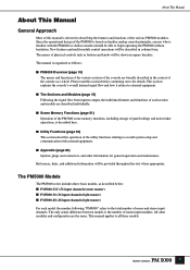
... with the PM4000 or similar consoles should be shown in column form. The PM5000 Models The PM5000 series includes three basic models, as described below: ■ PM5000-52C (52 input channels/center master) ■ PM5000-36 (36 input channels/right master) ■ PM5000-28 (28 input channels/right master) For each section and module are described...
... with the PM4000 or similar consoles should be shown in column form. The PM5000 Models The PM5000 series includes three basic models, as described below: ■ PM5000-52C (52 input channels/center master) ■ PM5000-36 (36 input channels/right master) ■ PM5000-28 (28 input channels/right master) For each section and module are described...

Owner's Manual
Page 9
...Basic Operation 45 Meter Bridge 47 Digital Control Section 49 Control Functions 49 Scene Memory Functions 51 Overview 51 Fade Time 52 Scene Store 53 Scene Recall 53 Title Edit 54 The Preview Function 55 Utility Functions 56 Overview 56 Common Operations ... ...........84 Module Removal and Replacement 84 Input Transformer Installation 86 Internal Switch Settings For Each module 88 Connector Pin Assignments 92 PM5000 Self-diagnostic Function 93 Initializing the Internal Memory 93 Error Messages 94 Troubleshooting 95 Specifications 96 1. Others 98 MIDI Data Format...
...Basic Operation 45 Meter Bridge 47 Digital Control Section 49 Control Functions 49 Scene Memory Functions 51 Overview 51 Fade Time 52 Scene Store 53 Scene Recall 53 Title Edit 54 The Preview Function 55 Utility Functions 56 Overview 56 Common Operations ... ...........84 Module Removal and Replacement 84 Input Transformer Installation 86 Internal Switch Settings For Each module 88 Connector Pin Assignments 92 PM5000 Self-diagnostic Function 93 Initializing the Internal Memory 93 Error Messages 94 Troubleshooting 95 Specifications 96 1. Others 98 MIDI Data Format...

Owner's Manual
Page 15
... simultaneously. NOTE In order to use phantom power, the rear-panel [+48V MASTER] switch must be carried out here. Mono Input Module Stereo Input Module 1 1 4 3 3 2 52 5 1 [+48V] Switch Engage this switch is engaged a 26-db pad is on . The arrows indicate controls and indicators that differ between the mono and stereo...
... simultaneously. NOTE In order to use phantom power, the rear-panel [+48V MASTER] switch must be carried out here. Mono Input Module Stereo Input Module 1 1 4 3 3 2 52 5 1 [+48V] Switch Engage this switch is engaged a 26-db pad is on . The arrows indicate controls and indicators that differ between the mono and stereo...

Owner's Manual
Page 20
... maintain the level of the channel fader. ∞ VCA Indicators 1~12 Indicate the VCA groups to specify target channels when setting fade time parameters (page 52). NOTE Using the VCA CUE function, the post-fader channel signal can also be monitored. The channel faders can be assigned to prevent the corresponding...
... maintain the level of the channel fader. ∞ VCA Indicators 1~12 Indicate the VCA groups to specify target channels when setting fade time parameters (page 52). NOTE Using the VCA CUE function, the post-fader channel signal can also be monitored. The channel faders can be assigned to prevent the corresponding...

Owner's Manual
Page 52
... [ALPHABET] Switch Engage the [TITLE] switch when you want to edit the title of the current scene as setting the scene fade times (page 52). 50 Right dot: The panel settings are used to increment or decrement scene numbers or parameter values. Digital Control Section 1 Scene Display (3 Digits ...+ 3 Dots) When the PM5000 scene memory function is used to enter scene numbers and titles, the [CLEAR/EXIT] key cancels scene number entry or deletes title characters, and...
... [ALPHABET] Switch Engage the [TITLE] switch when you want to edit the title of the current scene as setting the scene fade times (page 52). 50 Right dot: The panel settings are used to increment or decrement scene numbers or parameter values. Digital Control Section 1 Scene Display (3 Digits ...+ 3 Dots) When the PM5000 scene memory function is used to enter scene numbers and titles, the [CLEAR/EXIT] key cancels scene number entry or deletes title characters, and...

Owner's Manual
Page 54
... 10 seconds, in 0.2-second increments from 0.1 to 60 seconds, as required disengage the ASSIGN MODE [FADE TIME] switch (its indicator lights (at the same time). 52 Please note that if you recall a different scene before performing the scene store procedure the fade time settings you can individually specify the faders to...
... 10 seconds, in 0.2-second increments from 0.1 to 60 seconds, as required disengage the ASSIGN MODE [FADE TIME] switch (its indicator lights (at the same time). 52 Please note that if you recall a different scene before performing the scene store procedure the fade time settings you can individually specify the faders to...

Owner's Manual
Page 81
...be recalled directly from multiple external MIDI devices. MSB and LSB - In the same way scene recall operations performed on the PM5000. Control Change Control change commands can be always set the MIDI channel to the number of external MIDI devices. For example...#99) Value (hex) 30 1 30 1 22 2 22 2 1-5, 7-31 0 33-37, 39-63 1-5, 7-23 1 33-37, 39-55 1-5, 7-31 1-5, 7-23 0x0000(-∞) ~ 0x3FFF(+10dB) 12 3 12 3 52 4 12 4 8 4 4 4 8 4 2 4 1 4 12 5 8 5 1-5, 7-13 2 33-37, 39-45 1-5, 7-23, 33-37, 39-55 3 64-75 3 76-83 3 84-87 3 88-95 3 ...
...be recalled directly from multiple external MIDI devices. MSB and LSB - In the same way scene recall operations performed on the PM5000. Control Change Control change commands can be always set the MIDI channel to the number of external MIDI devices. For example...#99) Value (hex) 30 1 30 1 22 2 22 2 1-5, 7-31 0 33-37, 39-63 1-5, 7-23 1 33-37, 39-55 1-5, 7-31 1-5, 7-23 0x0000(-∞) ~ 0x3FFF(+10dB) 12 3 12 3 52 4 12 4 8 4 4 4 8 4 2 4 1 4 12 5 8 5 1-5, 7-13 2 33-37, 39-45 1-5, 7-23, 33-37, 39-55 3 64-75 3 76-83 3 84-87 3 88-95 3 ...

Owner's Manual
Page 97
... It takes a while for those channels (page 67)? • Has a fade time been specified (page 52)? 95 Also are changed. Files exceeding this case monitor output will be display by the PM5000. • Is INPUT SOLO SAFE engaged for the faders to stop moving when a scene is recalled. Panel displays...the [CUE] switch of the above check out OK and the power still won 't light. Can't save data to 128 files on , contact your Yamaha dealer or service center. • Are you attempting to save to a read-only scene number (000~009)? • Is the memory protect function turned ...
... It takes a while for those channels (page 67)? • Has a fade time been specified (page 52)? 95 Also are changed. Files exceeding this case monitor output will be display by the PM5000. • Is INPUT SOLO SAFE engaged for the faders to stop moving when a scene is recalled. Panel displays...the [CUE] switch of the above check out OK and the power still won 't light. Can't save data to 128 files on , contact your Yamaha dealer or service center. • Are you attempting to save to a read-only scene number (000~009)? • Is the memory protect function turned ...

Owner's Manual
Page 104
... EQ Block 16 EQ Controls 16 [EQ] Switch 16 Error Messages 94 Expansion: Connecting to External Equipment 14 External Expansion Connectors 13 102 F Fade Time 52 Fader Mode 70 [FADER SAFE] Switch 20 Fader Start 73 Fan Switch 13 Fan Vents 13 Format 60 G G/A (Group/Aux) Master Module 31 G/A (Group/Aux...
... EQ Block 16 EQ Controls 16 [EQ] Switch 16 Error Messages 94 Expansion: Connecting to External Equipment 14 External Expansion Connectors 13 102 F Fade Time 52 Fader Mode 70 [FADER SAFE] Switch 20 Fader Start 73 Fan Switch 13 Fan Vents 13 Format 60 G G/A (Group/Aux) Master Module 31 G/A (Group/Aux...