

Block Diagram
Page 1
... +12V +48V +48V-ON +48V PHANTOM MASTER LED LED LAMP PANEL LED DIMMER OUTPUT METER DIMMER LAMP DIMMER LAMP-ON 12V LAMP ON PREVIEW PREVIEW PM5000 Level Diagram +30dBu +20dBu PAD: ON (26dB) GAIN: Min. [+16dBu] +10dBu 0dBu -10dBu PAD: OFF (0dB) GAIN: Min. [-10dBu] -20dBu -...[+4dBu] MONITOR OUT [+4dBu] PHONES OUT [100mW@8Ω] +30dBu +20dBu +10dBu 0dBu -10dBu -20dBu -30dBu -40dBu -50dBu -60dBu PM5000 Block Diagram PM5000-52C :1~48 PM5000-36 :1~32 PM5000-28 :1~24 MONO INPUT [-60~+16dBu] +48V from Phantom Master PAD HA1 HA2 0dB 26dB GAIN Trim 26dB 0dB 26dB [0dB] INV ...
... +12V +48V +48V-ON +48V PHANTOM MASTER LED LED LAMP PANEL LED DIMMER OUTPUT METER DIMMER LAMP DIMMER LAMP-ON 12V LAMP ON PREVIEW PREVIEW PM5000 Level Diagram +30dBu +20dBu PAD: ON (26dB) GAIN: Min. [+16dBu] +10dBu 0dBu -10dBu PAD: OFF (0dB) GAIN: Min. [-10dBu] -20dBu -...[+4dBu] MONITOR OUT [+4dBu] PHONES OUT [100mW@8Ω] +30dBu +20dBu +10dBu 0dBu -10dBu -20dBu -30dBu -40dBu -50dBu -60dBu PM5000 Block Diagram PM5000-52C :1~48 PM5000-36 :1~32 PM5000-28 :1~24 MONO INPUT [-60~+16dBu] +48V from Phantom Master PAD HA1 HA2 0dB 26dB GAIN Trim 26dB 0dB 26dB [0dB] INV ...
Owner's Manual
Page 7
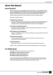
...of the console as described below: ■ PM5000-52C (52 input channels/center master) ■ PM5000-36 (36 input channels/right master) ■ PM5000-28 (28 input channels/right master) For each model the number following "PM5000" refers to output, the individual features and functions...be described in square brackets. References, hints, and additional information will be provided throughout the text where appropriate. The PM5000 Models The PM5000 series includes three basic models, as a whole. All other information for general operation and maintenance. This manual applies ...
...of the console as described below: ■ PM5000-52C (52 input channels/center master) ■ PM5000-36 (36 input channels/right master) ■ PM5000-28 (28 input channels/right master) For each model the number following "PM5000" refers to output, the individual features and functions...be described in square brackets. References, hints, and additional information will be provided throughout the text where appropriate. The PM5000 Models The PM5000 series includes three basic models, as a whole. All other information for general operation and maintenance. This manual applies ...

Owner's Manual
Page 10
... input channel is made up of two separate hardware components: an "input channel module" and a "fader module." PM5000 Overview PM5000 Overview Panel Layout The layout of the PM5000's functional sections in all of the console's input modules make up the "input channel section." Each section further contains "blocks" of the console, while ... For example, all other models it is shown below. Each input channel is made up of an "EQ block," a "fader block," and others. Top Panel PM5000-52C PM5000-28 10 In the PM500052C the master output section is located in the center of functions.
... input channel is made up of two separate hardware components: an "input channel module" and a "fader module." PM5000 Overview PM5000 Overview Panel Layout The layout of the PM5000's functional sections in all of the console's input modules make up the "input channel section." Each section further contains "blocks" of the console, while ... For example, all other models it is shown below. Each input channel is made up of an "EQ block," a "fader block," and others. Top Panel PM5000-52C PM5000-28 10 In the PM500052C the master output section is located in the center of functions.

Owner's Manual
Page 12
...Card Slot The console's memory card reader is provided to physically reach the recalled settings. Rear Panel PM5000-52C ! ∞ ^% $ PM5000-28 ! # @ ¡º @ ! ∞ ^% $ NOTE All PM5000 inputs and outputs are also provided. This section also provides access to utility functions that will take ... switches function in this section is specified via a utility mode function. 8 Digital Control Section (page 49) The PM5000's digital control features are also provided to display the status of the digital control section can use CF (CompactFlash) memory cards ...
...Card Slot The console's memory card reader is provided to physically reach the recalled settings. Rear Panel PM5000-52C ! ∞ ^% $ PM5000-28 ! # @ ¡º @ ! ∞ ^% $ NOTE All PM5000 inputs and outputs are also provided. This section also provides access to utility functions that will take ... switches function in this section is specified via a utility mode function. 8 Digital Control Section (page 49) The PM5000's digital control features are also provided to display the status of the digital control section can use CF (CompactFlash) memory cards ...

Owner's Manual
Page 13
...and B CASCADE connectors, a D-sub 25-pin GPI connector, and MIDI IN/OUT/THRU connectors for the console's internal cooling fans (4 locations on the PM5000-52C, 3 on or off . ¡ Fan Vents These are the stereo and mono master outputs (ST OUT, MONO (C)). º Lamp Connectors The ...supplied gooseneck lamps can be connected here (4 connectors on the PM5000-52C, 3 on the meter bridge. Please check the supplied block diagram for all input channels. You can use A and B simultaneously for the L and...
...and B CASCADE connectors, a D-sub 25-pin GPI connector, and MIDI IN/OUT/THRU connectors for the console's internal cooling fans (4 locations on the PM5000-52C, 3 on or off . ¡ Fan Vents These are the stereo and mono master outputs (ST OUT, MONO (C)). º Lamp Connectors The ...supplied gooseneck lamps can be connected here (4 connectors on the PM5000-52C, 3 on the meter bridge. Please check the supplied block diagram for all input channels. You can use A and B simultaneously for the L and...

Owner's Manual
Page 100
...S=GND). reserves the right to Environments: E1, E2, E3 and E4 98 * Specifications and descriptions in every locale, please check with your Yamaha dealer. before Clip 150Ω 600Ω Lines +4dBu (1.23V) +24dBu (12.3V) XLR-3-32 type 150Ω 600Ω Lines +4dBu...With Nominal Output Level *3 Connector In Mixer *2 Nominal Max. Others 3.1 Included Accessories Power Supply Connection Cable (3.6m) Gooseneck Lamps (4 for the PM5000-52C, 3 for PM4000/PM3500 series) VCA GROUP 1-8, MUTE GROUP 1-8, CUE SOLO GPI (General Purpose Interface) MIDI IN OUT THRU DC POWER IN Dsub...
...S=GND). reserves the right to Environments: E1, E2, E3 and E4 98 * Specifications and descriptions in every locale, please check with your Yamaha dealer. before Clip 150Ω 600Ω Lines +4dBu (1.23V) +24dBu (12.3V) XLR-3-32 type 150Ω 600Ω Lines +4dBu...With Nominal Output Level *3 Connector In Mixer *2 Nominal Max. Others 3.1 Included Accessories Power Supply Connection Cable (3.6m) Gooseneck Lamps (4 for the PM5000-52C, 3 for PM4000/PM3500 series) VCA GROUP 1-8, MUTE GROUP 1-8, CUE SOLO GPI (General Purpose Interface) MIDI IN OUT THRU DC POWER IN Dsub...