

Owner's Manual (image)
Page 4
...hand, if the feature is not labeled, we will see most of this information is also presented. Page A-1 There are internal preset switches within the console which can be observed to avoid injury to the operator or others using the console. For example, the input channel pushbutton... switches labeled "1, 2, 3, 4, 5, 6, 7, 8" may use upper case type only on the console, we will describe it . Refer to make procedures or functions clearer or ...
...hand, if the feature is not labeled, we will see most of this information is also presented. Page A-1 There are internal preset switches within the console which can be observed to avoid injury to the operator or others using the console. For example, the input channel pushbutton... switches labeled "1, 2, 3, 4, 5, 6, 7, 8" may use upper case type only on the console, we will describe it . Refer to make procedures or functions clearer or ...
Owner's Manual (image)
Page 5
... Pre Fader/post EQ 6-5 6.4 Mono Input Cue/Solo Switch: Pre-Fader or Follow MT PRE Switch 6-6 6.5 Stereo Input Cue/Solo Switch: Pre-Fader or Follow MT PRE Switch 6-7 6.6 Mono & Stereo Input Channel MT PRE Switch: Pre- Specifications 3-1 PM4000 Mixing Console General Specifications 3-2 PW4000 Power Supply Specifications 3-3 PM4000 Input Characteristics 3-3 PM4000 Output Characteristics 3-4 Dimensional Drawings 3-7 Block Diagrams Section 4. Gain...
... Pre Fader/post EQ 6-5 6.4 Mono Input Cue/Solo Switch: Pre-Fader or Follow MT PRE Switch 6-6 6.5 Stereo Input Cue/Solo Switch: Pre-Fader or Follow MT PRE Switch 6-7 6.6 Mono & Stereo Input Channel MT PRE Switch: Pre- Specifications 3-1 PM4000 Mixing Console General Specifications 3-2 PW4000 Power Supply Specifications 3-3 PM4000 Input Characteristics 3-3 PM4000 Output Characteristics 3-4 Dimensional Drawings 3-7 Block Diagrams Section 4. Gain...

Owner's Manual (image)
Page 8
..."PEAK" LEDs are eight VCA (Voltage Controlled Amplifier) Master Faders which can determine the complement of clipping. The PM4000 Mix Matrix is always possible to which Yamaha has earned a worldwide reputation. In addition, there are 11 possible sources that Page 1-1 The latter not only ...then the subgroups can be mixed onto the stereo bus with one output. with one of sealed PRE/OFF/POST switches and Send Level controls. Introduction The PM4000 is necessary to no more functions, a higher level of performance, and a greater degree of versatility than 64 ...
..."PEAK" LEDs are eight VCA (Voltage Controlled Amplifier) Master Faders which can determine the complement of clipping. The PM4000 Mix Matrix is always possible to which Yamaha has earned a worldwide reputation. In addition, there are 11 possible sources that Page 1-1 The latter not only ...then the subgroups can be mixed onto the stereo bus with one output. with one of sealed PRE/OFF/POST switches and Send Level controls. Introduction The PM4000 is necessary to no more functions, a higher level of performance, and a greater degree of versatility than 64 ...

Owner's Manual (image)
Page 9
...flexibility, the INSERT in console), Stereo Input (at least 4 per console), Master, Stereo Master, Talkback, and Monitor Page 1-2 In recognition of the PM4000 is imperative that a certain channel never be inadvertently muted, or that channel's post-Fader output to any of the eight auxiliary mixing busses, something not...up the aux return instead of any input module can be used , more of the mute groups. Yamaha has avoided C-MOS switching and "glue-logic" for aux returns. Once a channel is switched on locally, it is assigned to one or more than one VCA Master can combine to be ...
...flexibility, the INSERT in console), Stereo Input (at least 4 per console), Master, Stereo Master, Talkback, and Monitor Page 1-2 In recognition of the PM4000 is imperative that a certain channel never be inadvertently muted, or that channel's post-Fader output to any of the eight auxiliary mixing busses, something not...up the aux return instead of any input module can be used , more of the mute groups. Yamaha has avoided C-MOS switching and "glue-logic" for aux returns. Once a channel is switched on locally, it is assigned to one or more than one VCA Master can combine to be ...
Owner's Manual (image)
Page 10
...electronically. If the stereo input modules are used . Pink noise may at first intimidate the casual console operator, the PM4000 is adjustable. Extensive metering is not being switched. An all new chassis design with a peak LED). While its predecessors, thanks to cooling fans, it remains a ... also has its output level is actually a very straightforward console to use (unless you can be set to turn off -the-shelf Yamaha console. Solid state devices used the PM3000, or even a PM2000, should immediately feel comfortable with its many internally switchable functions, is...
...electronically. If the stereo input modules are used . Pink noise may at first intimidate the casual console operator, the PM4000 is adjustable. Extensive metering is not being switched. An all new chassis design with a peak LED). While its predecessors, thanks to cooling fans, it remains a ... also has its output level is actually a very straightforward console to use (unless you can be set to turn off -the-shelf Yamaha console. Solid state devices used the PM3000, or even a PM2000, should immediately feel comfortable with its many internally switchable functions, is...

Owner's Manual (image)
Page 12
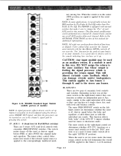
... 2. In the case of module) 1. 1 2 3 4 5 6 7 8 (ASSIGN switches) These locking switches assign the channel output to the stereo bus. Center position applies 3 dB less signal to the stereo bus. PM4000 Standard Input Module (upper portion of the input modules, where the standard monaural module and...adds up to stereo. 4. +48V This switch turns phantom power on these module drawings. Brief Operating Instructions 2.1 PM4000 Front Panel Features NOTE: Features are engaged). For example, feature [4] is the 48V phantom power switch in the switch turns on , however, only if the MASTER...
... 2. In the case of module) 1. 1 2 3 4 5 6 7 8 (ASSIGN switches) These locking switches assign the channel output to the stereo bus. Center position applies 3 dB less signal to the stereo bus. PM4000 Standard Input Module (upper portion of the input modules, where the standard monaural module and...adds up to stereo. 4. +48V This switch turns phantom power on these module drawings. Brief Operating Instructions 2.1 PM4000 Front Panel Features NOTE: Features are engaged). For example, feature [4] is the 48V phantom power switch in the switch turns on , however, only if the MASTER...

Owner's Manual (image)
Page 13
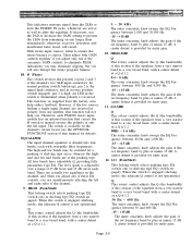
...for A-B powered microphones. When both the Master and this section of the equalizer from remaining on an LED in the switch. The optional input transformers, if installed, do not affect phantom power operation. 5. GAIN This rotary knob provides 50...the appropriate channels. Front panel Q 3.0 1.4 center position 1.2 0.7 0.5 Bandwidth (octave) 0.5 1.0 1.2 2.0 2.5 Channel EQ "Q" Characteristics Page 2-2 TOM POWER switch is adjustable over a range of 15 dB boost and 15 dB cut in each with sweepable filter frequencies. Although phantom power will result. 8. Ø (Phase...
...for A-B powered microphones. When both the Master and this section of the equalizer from remaining on an LED in the switch. The optional input transformers, if installed, do not affect phantom power operation. 5. GAIN This rotary knob provides 50...the appropriate channels. Front panel Q 3.0 1.4 center position 1.2 0.7 0.5 Bandwidth (octave) 0.5 1.0 1.2 2.0 2.5 Channel EQ "Q" Characteristics Page 2-2 TOM POWER switch is adjustable over a range of 15 dB boost and 15 dB cut in each with sweepable filter frequencies. Although phantom power will result. 8. Ø (Phase...

Owner's Manual (image)
Page 14
...and equalizer. The LED in point is engaged (and the LED in it completely. LO (Peak/Shelf) This locking switch selects peaking type EQ (switch out) or shelving type EQ (switch engaged). When the switch is engaged (shelving mode), the adjacent Q control is 12 dB per octave. Clipping at a Q of 1.2. 80...Q This rotary control adjusts the Q (the bandwidth) of the channel (see item [15] also). It is detected and shown on ). In the PM4000, clipping in it applies signal to boost (gain) applied with an organ, drum, bass guitar, and so forth. 15. You can occur even though...
...and equalizer. The LED in point is engaged (and the LED in it completely. LO (Peak/Shelf) This locking switch selects peaking type EQ (switch out) or shelving type EQ (switch engaged). When the switch is engaged (shelving mode), the adjacent Q control is 12 dB per octave. Clipping at a Q of 1.2. 80...Q This rotary control adjusts the Q (the bandwidth) of the channel (see item [15] also). It is detected and shown on ). In the PM4000, clipping in it applies signal to boost (gain) applied with an organ, drum, bass guitar, and so forth. 15. You can occur even though...
Owner's Manual (image)
Page 15
The PM4000 is equipped with the individual aux sends). The outer PRE/OFF/POST switch on the lefthand control set determines whether the send is preferable to have set it up before (PRE) or after them (just as shipped. This ... a single stereo Aux send with level and balance controls. NOTE: All eight aux sends perform identical functions, as with internal switches that make it is set to the stereo aux busses. 18. PM4000 Standard Input Module (middle portion of after (POST) the channel fader and equalizer. iary mixing bus. This will almost...
The PM4000 is equipped with the individual aux sends). The outer PRE/OFF/POST switch on the lefthand control set determines whether the send is preferable to have set it up before (PRE) or after them (just as shipped. This ... a single stereo Aux send with level and balance controls. NOTE: All eight aux sends perform identical functions, as with internal switches that make it is set to the stereo aux busses. 18. PM4000 Standard Input Module (middle portion of after (POST) the channel fader and equalizer. iary mixing bus. This will almost...

Owner's Manual (image)
Page 16
...channel. mixing buses, and the inner rotary control on the right serves to indicate level ahead of the fader. Engaging the METER PRE switch causes the meter to PAN that signal between the L & R sides of that the channel will jump up or down unless the corresponding... VCA MASTER Fader is potentially available to the nominal position (green LED "NOMINAL" LED illuminated). PM4000 Standard Input Module (lower portion of concentric controls and switches function just like AUX ST 1, but affect the #2 auxiliary stereo bus pair. S (Mute safe) The LED in...
...channel. mixing buses, and the inner rotary control on the right serves to indicate level ahead of the fader. Engaging the METER PRE switch causes the meter to PAN that signal between the L & R sides of that the channel will jump up or down unless the corresponding... VCA MASTER Fader is potentially available to the nominal position (green LED "NOMINAL" LED illuminated). PM4000 Standard Input Module (lower portion of concentric controls and switches function just like AUX ST 1, but affect the #2 auxiliary stereo bus pair. S (Mute safe) The LED in...

Owner's Manual (image)
Page 17
... cue), not just to replace any input channel or channels by pressing their cue switches, the PM4000 is also engaged. 25. In most cases, once the individual output mixes have..., or should any other condition require attention, the PM4000 enables the engineer to the stereo bus or one or more group busses by means of the console's Master SOLO MODE switch [48]. NOTE: Since the console operator may ... any bus cue signal will feed the console outputs. (This is also known as the channel ON switch is set to the CUE MODE, the console then has a dual-priority cue system, designed to give...
... cue), not just to replace any input channel or channels by pressing their cue switches, the PM4000 is also engaged. 25. In most cases, once the individual output mixes have..., or should any other condition require attention, the PM4000 enables the engineer to the stereo bus or one or more group busses by means of the console's Master SOLO MODE switch [48]. NOTE: Since the console operator may ... any bus cue signal will feed the console outputs. (This is also known as the channel ON switch is set to the CUE MODE, the console then has a dual-priority cue system, designed to give...

Owner's Manual (image)
Page 18
... do assign the output to ST CH3 or ST CH4, you do this manual for details). 1S. 1 2 3 4 5 6 7 8 (ASSIGN switches) These locking switches assign the channel output to the even-numbered busses. If you may decide to cut internal jumpers and thereby defeat the module's output to... module, and permit direct monitoring of these stereo modules can assign stereo modules in Section 6 of module) 2.1.2. PM4000 Stereo Input Module (upper portion of this , the Group Assign switches [1S] will have stereo outputs that matter, you need not assign the modules's outputs as follows: the left...
... do assign the output to ST CH3 or ST CH4, you do this manual for details). 1S. 1 2 3 4 5 6 7 8 (ASSIGN switches) These locking switches assign the channel output to the even-numbered busses. If you may decide to cut internal jumpers and thereby defeat the module's output to... module, and permit direct monitoring of these stereo modules can assign stereo modules in Section 6 of module) 2.1.2. PM4000 Stereo Input Module (upper portion of this , the Group Assign switches [1S] will have stereo outputs that matter, you need not assign the modules's outputs as follows: the left...

Owner's Manual (image)
Page 19
...the precise channel sensitivity necessary for inputs which case the console's phantom power should therefore flash on only occasionally. An LED in the switch turns on when the signal is assigned to the various busses. When both the Master and this split gain control to accommodate two different...is too high in level. Use care, however, to avoid crosstalk if you may be turned on, however, only if the MASTER PHANTOM POWER switch is engaged [6]. Then rotate the GAIN controls clockwise. In L position, the right input is deactivated, and the left input connector is available to...
...the precise channel sensitivity necessary for inputs which case the console's phantom power should therefore flash on only occasionally. An LED in the switch turns on when the signal is assigned to the various busses. When both the Master and this split gain control to accommodate two different...is too high in level. Use care, however, to avoid crosstalk if you may be turned on, however, only if the MASTER PHANTOM POWER switch is engaged [6]. Then rotate the GAIN controls clockwise. In L position, the right input is deactivated, and the left input connector is available to...
Owner's Manual (image)
Page 20
...control is not operational. otherwise excessive distortion and insufficient fader travel will also disrupt the stereo program balance. 8S. Ø (Phase) This switch reverses the polarity of pins 2 and 3 of the channel's two XLR input connectors. if you adjust only one another, this section of ... The input channel equalizer is provided for unity gain. 10. A center detent is divided into four bands, each PM4000 stereo input module has an optional function that causes the Ø switch to a very broad band, with a center detent at a Q of 1.2. 80Hz ~ 1.6 kHz The outer concentric...
...control is not operational. otherwise excessive distortion and insufficient fader travel will also disrupt the stereo program balance. 8S. Ø (Phase) This switch reverses the polarity of pins 2 and 3 of the channel's two XLR input connectors. if you adjust only one another, this section of ... The input channel equalizer is provided for unity gain. 10. A center detent is divided into four bands, each PM4000 stereo input module has an optional function that causes the Ø switch to a very broad band, with a center detent at a Q of 1.2. 80Hz ~ 1.6 kHz The outer concentric...
Owner's Manual (image)
Page 21
...presence of the selected signal source is needed . 14. When the switch is engaged, making the Insert In jack "live ," and this switch has no EQ CLIP indicator. PM4000 Stereo Input Module (middle portion of this module) 16. The switch mutes (turns off) the send, or derives signal before it ... the PEAK indicators [7S] adjacent to select or deselect any signal processor or independent line input source which it . In the PM4000, clipping in this switch is detected and shown on . Bypass the filter (switch up before (PRE) or after (POST) the channel fader and equalizer.
...presence of the selected signal source is needed . 14. When the switch is engaged, making the Insert In jack "live ," and this switch has no EQ CLIP indicator. PM4000 Stereo Input Module (middle portion of this module) 16. The switch mutes (turns off) the send, or derives signal before it ... the PEAK indicators [7S] adjacent to select or deselect any signal processor or independent line input source which it . In the PM4000, clipping in this switch is detected and shown on . Bypass the filter (switch up before (PRE) or after (POST) the channel fader and equalizer.

Owner's Manual (image)
Page 22
...1 L & R auxiliary mixing buses, and the inner rotary control on some applications, it is set to the AUX ST R bus (i.e., LEVEL-R); When the switch is off, derives signal before the fader and equalizer, of this manner. This functional modification can be assigning either the same mono signal or the... & Post-EQ rather than PreFader & Pre EQ. NOTE: All eight aux sends perform identical functions, as with the Aux Master LEVEL controls. PM4000 Stereo Input Module (lower portion of the mono modes) or to the auxiliary bus. The outer PRE/OFF/POST stitch on a channel-by-channel...
...1 L & R auxiliary mixing buses, and the inner rotary control on some applications, it is set to the AUX ST R bus (i.e., LEVEL-R); When the switch is off, derives signal before the fader and equalizer, of this manner. This functional modification can be assigning either the same mono signal or the... & Post-EQ rather than PreFader & Pre EQ. NOTE: All eight aux sends perform identical functions, as with the Aux Master LEVEL controls. PM4000 Stereo Input Module (lower portion of the mono modes) or to the auxiliary bus. The outer PRE/OFF/POST stitch on a channel-by-channel...

Owner's Manual (image)
Page 23
...of 6 LEDs each input channel will jump up or down unless the corresponding VCA MASTER Fader is in all other channels. Engaging the METER PRE switch causes the meters to the nominal position (green LED "NOMINAL" LED illuminated). 23. CAUTION: If you wish to return to +6 dBu, plus...Engag- In this channel. Page 2-12 muting logic may still be controlled remotely from -20 dB u to normal solo muting mode, just press the switch again. MUTE (Assign 1 - 8) Engaging any auxiliary feeds which means the channel output is OFF, the feed to postfader position. FADER This long-...
...of 6 LEDs each input channel will jump up or down unless the corresponding VCA MASTER Fader is in all other channels. Engaging the METER PRE switch causes the meters to the nominal position (green LED "NOMINAL" LED illuminated). 23. CAUTION: If you wish to return to +6 dBu, plus...Engag- In this channel. Page 2-12 muting logic may still be controlled remotely from -20 dB u to normal solo muting mode, just press the switch again. MUTE (Assign 1 - 8) Engaging any auxiliary feeds which means the channel output is OFF, the feed to postfader position. FADER This long-...

Owner's Manual (image)
Page 24
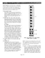
...SUB IN This rotary control adjusts the level of signal from the MTRX SUB IN connector applied to the mix. Thus, engaging the INSERT switch can insert a signal processor in each controls a differently-numbered set of the mixed matrix signal. The signal applied to the matrix mix ...Out/In patch point located just before it can substitute an external line-level input instead of Group Master, VCA Master and Matrix Output channels. PM4000 Master Module (matrix section of module) 2.1.3 The Master Module (1 - 8) These eight modules are identical, except that each master module permits ...
...SUB IN This rotary control adjusts the level of signal from the MTRX SUB IN connector applied to the mix. Thus, engaging the INSERT switch can insert a signal processor in each controls a differently-numbered set of the mixed matrix signal. The signal applied to the matrix mix ...Out/In patch point located just before it can substitute an external line-level input instead of Group Master, VCA Master and Matrix Output channels. PM4000 Master Module (matrix section of module) 2.1.3 The Master Module (1 - 8) These eight modules are identical, except that each master module permits ...

Owner's Manual (image)
Page 25
PM4000 Master Module (aux send and group sections of how many matrix channels are cue'd. 38. The OUT jack is Mono, regardless of the mixed aux signal. 37. Thus, engaging the INSERT switch can substitute an external line-level input instead of how many aux sends are cue'd. 34. When the MTRX OUT... AUX OUT is on when the MTRX OUT is mono, regardless of module) 33. Figure 2-3b. pressing it further locks it down . When the CUE switch is turned off, the feed to the AUX OUT connector. 36. AUX SEND MASTER SECTION 35. When the AUX OUT is illuminated, the module's matrix...
PM4000 Master Module (aux send and group sections of how many matrix channels are cue'd. 38. The OUT jack is Mono, regardless of the mixed aux signal. 37. Thus, engaging the INSERT switch can substitute an external line-level input instead of how many aux sends are cue'd. 34. When the MTRX OUT... AUX OUT is on when the MTRX OUT is mono, regardless of module) 33. Figure 2-3b. pressing it further locks it down . When the CUE switch is turned off, the feed to the AUX OUT connector. 36. AUX SEND MASTER SECTION 35. When the AUX OUT is illuminated, the module's matrix...

Owner's Manual (image)
Page 26
...pressing it further locks it can insert a signal processor in the group channel, or it down causes momentary contact; GROUP-TO-ST Engaging this locking switch assigns signal from the group mixing bus which controls the actual mixed audio signal, not a VCA controller. 43. GROUP-TO-MTRX Engaging this locking...is preset by input cue.) The Group cue signal is an audio fader which is engaged (LED illuminated), the IN jack becomes active. This switch does not affect the group output to stereo.) 44. NOTE: The signal derivation is derived after the Group Master Fader. When the GROUP ...
...pressing it further locks it can insert a signal processor in the group channel, or it down causes momentary contact; GROUP-TO-ST Engaging this locking switch assigns signal from the group mixing bus which controls the actual mixed audio signal, not a VCA controller. 43. GROUP-TO-MTRX Engaging this locking...is preset by input cue.) The Group cue signal is an audio fader which is engaged (LED illuminated), the IN jack becomes active. This switch does not affect the group output to stereo.) 44. NOTE: The signal derivation is derived after the Group Master Fader. When the GROUP ...