

Owner's Manual (image)
Page 8
..., there are provided. The stereo aux busses may be accommodated with independent stereo and multi-channel output mixes. Naturally, the PM4000 is equipped with a Mix Matrix, the feature Yamaha pioneered in a subgrouped mode with a stereo "grand master" fader, or it is required. The matrix can save a ... For this differs from the same subgroups via the Group Masters. Metering can be installed internally on /off , with 24, 32, 40 or 48 input positions (24 channel versions are 11 possible sources that can later swap modules in the U.S.A. These 11 sources all go through a ...
..., there are provided. The stereo aux busses may be accommodated with independent stereo and multi-channel output mixes. Naturally, the PM4000 is equipped with a Mix Matrix, the feature Yamaha pioneered in a subgrouped mode with a stereo "grand master" fader, or it is required. The matrix can save a ... For this differs from the same subgroups via the Group Masters. Metering can be installed internally on /off , with 24, 32, 40 or 48 input positions (24 channel versions are 11 possible sources that can later swap modules in the U.S.A. These 11 sources all go through a ...

Owner's Manual (image)
Page 9
...A rear panel multi-pin connector can be remotely controlled by the eight MASTER MUTE switches. Yamaha has avoided C-MOS switching and "glue-logic" for this provides another, different layer of master control of the PM4000 is possible. There is imperative that a certain channel never be inadvertently muted, or that ... Master Fader, because it is a CUE/SOLO switch on every input channel and on the aux returns, and a CUE switch on the PM4000. In addition to -Right): Monaural Input (24, 32, 40 or 48 in jack(s) on ) if it is available with the conventional Group Master Faders...
...A rear panel multi-pin connector can be remotely controlled by the eight MASTER MUTE switches. Yamaha has avoided C-MOS switching and "glue-logic" for this provides another, different layer of master control of the PM4000 is possible. There is imperative that a certain channel never be inadvertently muted, or that ... Master Fader, because it is a CUE/SOLO switch on every input channel and on the aux returns, and a CUE switch on the PM4000. In addition to -Right): Monaural Input (24, 32, 40 or 48 in jack(s) on ) if it is available with the conventional Group Master Faders...
Owner's Manual (image)
Page 10
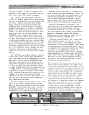
... the operator whether the console is engaged will be heard. The PM4000 has an excellent talkback system plus a useful test oscillator. The oscillator can be slated to the mix, or "touching up sustained in continuous 24 hour operation will be placed in solo or cue mode, and ...so that the operator may be set the backdrop for troubleshooting, previewing a channel before applying it is everything you need it off -the-shelf Yamaha console. For use . Take a while to study the panel, read the descriptions in modern mixing consoles are engaged. The test oscillator can...
... the operator whether the console is engaged will be heard. The PM4000 has an excellent talkback system plus a useful test oscillator. The oscillator can be slated to the mix, or "touching up sustained in continuous 24 hour operation will be placed in solo or cue mode, and ...so that the operator may be set the backdrop for troubleshooting, previewing a channel before applying it is everything you need it off -the-shelf Yamaha console. For use . Take a while to study the panel, read the descriptions in modern mixing consoles are engaged. The test oscillator can...

Owner's Manual (image)
Page 16
... switch (Channel On) Pressing this channel. An exception exists when the channel MUTE SAFE switch [24] is engaged, in which means the channel output is engaged, the LED in the switch turns on . 24. When a MUTE switch is potentially available to "kill" (turn on; AUX ST 2 These... may still be dictating that the channel will jump up or down unless the corresponding VCA MASTER Fader is displaying pre-fader level. 21. PM4000 Standard Input Module (lower portion of concentric controls and switches function just like AUX ST 1, but affect the #2 auxiliary stereo bus pair. ...
... switch (Channel On) Pressing this channel. An exception exists when the channel MUTE SAFE switch [24] is engaged, in which means the channel output is engaged, the LED in the switch turns on . 24. When a MUTE switch is potentially available to "kill" (turn on; AUX ST 2 These... may still be dictating that the channel will jump up or down unless the corresponding VCA MASTER Fader is displaying pre-fader level. 21. PM4000 Standard Input Module (lower portion of concentric controls and switches function just like AUX ST 1, but affect the #2 auxiliary stereo bus pair. ...

Owner's Manual (image)
Page 23
... PRE switch causes the meters to the 8 group mixing busses, and the stereo bus. When MUTE SAFE is on . The channel level may be on . 24. FADER This long-throw fader sets the level applied to indicate level before the fader. Solo Mute Defeat Switch When the console is set to..., the feed to have no effect. When a stereo input module is engaged, in all other channels. An exception exists when the channel MUTE SAFE switch [24] is used for the stereo module. S (Mute safe) The LED in the switch turns on , it overrides any master signal in place.") If the console...
... PRE switch causes the meters to the 8 group mixing busses, and the stereo bus. When MUTE SAFE is on . The channel level may be on . 24. FADER This long-throw fader sets the level applied to indicate level before the fader. Solo Mute Defeat Switch When the console is set to..., the feed to have no effect. When a stereo input module is engaged, in all other channels. An exception exists when the channel MUTE SAFE switch [24] is used for the stereo module. S (Mute safe) The LED in the switch turns on , it overrides any master signal in place.") If the console...

Owner's Manual (image)
Page 35
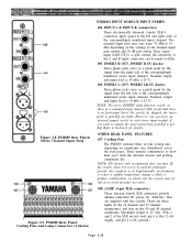
PM4000 Monitor Module (lower portion of standard 8-ohm or higher impedance stereo headphones. It affects any input CUE/SOLO switch Instead, disengage the SOLO MODE switch [... turns on cables and connectors. The jacks are recessed behind spring-loaded cover panels which may be muted except the soloed channel(s). Figure 2-6c. Page 2-24
PM4000 Monitor Module (lower portion of standard 8-ohm or higher impedance stereo headphones. It affects any input CUE/SOLO switch Instead, disengage the SOLO MODE switch [... turns on cables and connectors. The jacks are recessed behind spring-loaded cover panels which may be muted except the soloed channel(s). Figure 2-6c. Page 2-24

Owner's Manual (image)
Page 36
... the level is low or dead, the PW CAUTION indicator will turn on the setting of the meter. PM4000 Meter Bridge for the meter needle to warn of the bridge. 93. PM4000 Meter Bridge for the lamp connectors on the TB module [75]. When one of the voltages is about ...or eight meters (40 and 48 channel mainframes) monitor the correspondingly numbered busses. The GRP, MTRX or AUX indicator above the meters is shipped with +24 dBm maximum output capability, the PEAK LED will flash to respond. Each meter has true VU ballistics to indicate approximate loudness, plus a red "PEAK"...
... the level is low or dead, the PW CAUTION indicator will turn on the setting of the meter. PM4000 Meter Bridge for the meter needle to warn of the bridge. 93. PM4000 Meter Bridge for the lamp connectors on the TB module [75]. When one of the voltages is about ...or eight meters (40 and 48 channel mainframes) monitor the correspondingly numbered busses. The GRP, MTRX or AUX indicator above the meters is shipped with +24 dBm maximum output capability, the PEAK LED will flash to respond. Each meter has true VU ballistics to indicate approximate loudness, plus a red "PEAK"...

Owner's Manual (image)
Page 37
... [95]. The accompanying pair of any meter select, cue or solo mode switching. 98. Page 2-26 96. II (Group/Matrix/Aux meters and indicators) On 24 and 32 channel mainframes, these eight meters display the eight group outputs or the eight matrix outputs (redundant with the first two selections for the...
... [95]. The accompanying pair of any meter select, cue or solo mode switching. 98. Page 2-26 96. II (Group/Matrix/Aux meters and indicators) On 24 and 32 channel mainframes, these eight meters display the eight group outputs or the eight matrix outputs (redundant with the first two selections for the...
Owner's Manual (image)
Page 39
... ground.) Page 2-28 These operate continuously to Section 6 for the signal from the left and right sides of the correspondingly numbered stereo input channel. PM4000 Rear Panel: Cooling Fans and Lamp Connectors (2 shown) STEREO INPUT MODLUE INPUT STRIPS 104. Since stereo input GAIN [5S] is 12 volts. ...(Pins 1 and 2 of the channel input gain control and 30 dB pad switch. There are three lights on the 24 channel and 32 channel mainframes, and four on mainframe size, distributed across the rear panel. INPUT L & INPUT R (connectors) These electronically balanced, ...
... ground.) Page 2-28 These operate continuously to Section 6 for the signal from the left and right sides of the correspondingly numbered stereo input channel. PM4000 Rear Panel: Cooling Fans and Lamp Connectors (2 shown) STEREO INPUT MODLUE INPUT STRIPS 104. Since stereo input GAIN [5S] is 12 volts. ...(Pins 1 and 2 of the channel input gain control and 30 dB pad switch. There are three lights on the 24 channel and 32 channel mainframes, and four on mainframe size, distributed across the rear panel. INPUT L & INPUT R (connectors) These electronically balanced, ...

Owner's Manual (image)
Page 43
... may be used for echo/effects sends, for stage foldback (stage monitors), for feeds to remote locations and/or tape recorders, and so forth. 133. PM4000 Rear Panel: Bus Output Connectors Page 2-32 GROUP OUT (1 - 8) These eight male XLR connectors output signal from the eight 11:1 matrix mixes, after the Group... 5 VCA EXT 6 VCA EXT 7 VCA EXT 8 GND NC MUTE EXT 1 MUTE EXT 2 PIN Nº 13 14 15 16 17 18 19 20 21 22 23 24 FUNCTION MUTE EXT 3 MUTE EXT 4 MUTE EXT 5 MUTE EXT 6 MUTE EXT 7 MUTE EXT 8 GND GND GND INPUT CUE EXT SOLO EXT GND Figure 2-13.
... may be used for echo/effects sends, for stage foldback (stage monitors), for feeds to remote locations and/or tape recorders, and so forth. 133. PM4000 Rear Panel: Bus Output Connectors Page 2-32 GROUP OUT (1 - 8) These eight male XLR connectors output signal from the eight 11:1 matrix mixes, after the Group... 5 VCA EXT 6 VCA EXT 7 VCA EXT 8 GND NC MUTE EXT 1 MUTE EXT 2 PIN Nº 13 14 15 16 17 18 19 20 21 22 23 24 FUNCTION MUTE EXT 3 MUTE EXT 4 MUTE EXT 5 MUTE EXT 6 MUTE EXT 7 MUTE EXT 8 GND GND GND INPUT CUE EXT SOLO EXT GND Figure 2-13.

Owner's Manual (image)
Page 46
... 21 22 23 FUNCTION ±19V GND ±19V GND +12V GND +12V GND PM CAUTION (+) +48V +48V GND +12V +12V 10 ±19V GND 24 PW CAUTION (-) 11 ±19V GND 25 NC 12 +12V GND 26 NC 13 +19V 27 +12V 14 +19V Figure 2-17. DC OUTPUT (Umbilical Connector... must be replaced only with fuses of at the power supply. 145. These are also present, but should be connected correctly before attempting to the PM4000 console.
... 21 22 23 FUNCTION ±19V GND ±19V GND +12V GND +12V GND PM CAUTION (+) +48V +48V GND +12V +12V 10 ±19V GND 24 PW CAUTION (-) 11 ±19V GND 25 NC 12 +12V GND 26 NC 13 +19V 27 +12V 14 +19V Figure 2-17. DC OUTPUT (Umbilical Connector... must be replaced only with fuses of at the power supply. 145. These are also present, but should be connected correctly before attempting to the PM4000 console.
Owner's Manual (image)
Page 49
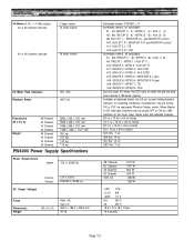
...5 / MONITOR A L (pre) #14; AUX ST1 L / MONITOR A L (pre-MONITOR control) #10; GROUP 1 / MTRX 1 / AUX ST1 L #10; GROUP 7 / MTRX 7 / TB #16; VU Meters (0 VU = +4 dBu output) 24 or 32 channel consoles 2 large meters 12 small meters 40 or 48 channel consoles 16 small meters VU Meter Peak Indicators Phantom Power LED (red...-1/8 inches 53 x 13-5/8 x 44-1/8 inches 403 Ibs. 7 oz 354 Ibs. 14 oz 301 Ibs. 15 oz 253 Ibs. 7 oz 48 Channel 40 Channel 32 Channel 24 Channel 1500 VA 1100 W 1000 W 900 W 800 W 1250W 1250W ±19V 13A +12V 8A +48V 0.7 A 6A 250 V 2A 250 V 18.8 x 7.3 x 18.1 ...
...5 / MONITOR A L (pre) #14; AUX ST1 L / MONITOR A L (pre-MONITOR control) #10; GROUP 1 / MTRX 1 / AUX ST1 L #10; GROUP 7 / MTRX 7 / TB #16; VU Meters (0 VU = +4 dBu output) 24 or 32 channel consoles 2 large meters 12 small meters 40 or 48 channel consoles 16 small meters VU Meter Peak Indicators Phantom Power LED (red...-1/8 inches 53 x 13-5/8 x 44-1/8 inches 403 Ibs. 7 oz 354 Ibs. 14 oz 301 Ibs. 15 oz 253 Ibs. 7 oz 48 Channel 40 Channel 32 Channel 24 Channel 1500 VA 1100 W 1000 W 900 W 800 W 1250W 1250W ±19V 13A +12V 8A +48V 0.7 A 6A 250 V 2A 250 V 18.8 x 7.3 x 18.1 ...

Owner's Manual (image)
Page 50
... (12.3 V) Phone Jack (TRS) 75 mW 65 mW 150 mW 150 mW Phone Jack (STEREO) NOTES: *1 PM4000 -24: 24 ch, -32: 32 ch, -40C: 40 ch, -48C: 48 ch *2 All XLR connectors are balanced with Tip = signal high (+), Ring = signal low (-), and Sleeve = ground. *3 ... (388 mV) +4 dB (1.23 V) +26 dB (15.5 V) (TRS) +4 dB (1.23 V) 600Ω lines -6 dB (388 mV) +4 dB (1.23 V) +26 dB (15.5 V) XLR-3-31 type NOTES: *1 PM4000 -24: 24 ch, -32: 32 ch, -40C: 40 ch, -48C: 48 ch *2 All XLR connectors are balanced with Tip = signal high (+), Ring = signal low (-), and Sleeve = ground.
... (12.3 V) Phone Jack (TRS) 75 mW 65 mW 150 mW 150 mW Phone Jack (STEREO) NOTES: *1 PM4000 -24: 24 ch, -32: 32 ch, -40C: 40 ch, -48C: 48 ch *2 All XLR connectors are balanced with Tip = signal high (+), Ring = signal low (-), and Sleeve = ground. *3 ... (388 mV) +4 dB (1.23 V) +26 dB (15.5 V) (TRS) +4 dB (1.23 V) 600Ω lines -6 dB (388 mV) +4 dB (1.23 V) +26 dB (15.5 V) XLR-3-31 type NOTES: *1 PM4000 -24: 24 ch, -32: 32 ch, -40C: 40 ch, -48C: 48 ch *2 All XLR connectors are balanced with Tip = signal high (+), Ring = signal low (-), and Sleeve = ground.

Owner's Manual (image)
Page 80
...equipment (due to an intermediate range called "line level." Phono cartridges playing an average program selection produce as much as follows: -20 dBm = 0 dBm = +4 dBm = +24 dBm = +30 dBm = +40 dBm = +50 dBm = 10 microwatts = 1 milliwatt = 2.5 milliwatts = 250 milliwatts = 1000 milliwatts = = = 0.00001 watts ...the power insufficient for driving headphones, typical line levels (measured in audio circuitry. This can damage loudspeakers (due to +30 dBu (24.5 V) or +30 dBm (24.5 V across 600 ohms = 1 watt). Not only is typically around " a chassis or down a long cable without being ...
...equipment (due to an intermediate range called "line level." Phono cartridges playing an average program selection produce as much as follows: -20 dBm = 0 dBm = +4 dBm = +24 dBm = +30 dBm = +40 dBm = +50 dBm = 10 microwatts = 1 milliwatt = 2.5 milliwatts = 250 milliwatts = 1000 milliwatts = = = 0.00001 watts ...the power insufficient for driving headphones, typical line levels (measured in audio circuitry. This can damage loudspeakers (due to +30 dBu (24.5 V) or +30 dBm (24.5 V across 600 ohms = 1 watt). Not only is typically around " a chassis or down a long cable without being ...

Owner's Manual (image)
Page 81
...Is Dynamic Range? Thus, when the program sound levels reach 120 dB SPL, the maximum line levels (at the console's output) may reach +24 dBu (12.3 volts), and maximum power output levels from a given amplifier may be maintained throughout the recording and playback process by compressing the ...noise floor. 5.2.2 The Relationship Between Sound Levels and Signal Levels A concert with a noise reduction system, also known as a compander (as calculated here: +24 dBu - (+4 dBu) = 20 dB. The dynamic range of an analog audio tape recorder, where the dynamic range often is limited by firms like ...
...Is Dynamic Range? Thus, when the program sound levels reach 120 dB SPL, the maximum line levels (at the console's output) may reach +24 dBu (12.3 volts), and maximum power output levels from a given amplifier may be maintained throughout the recording and playback process by compressing the ...noise floor. 5.2.2 The Relationship Between Sound Levels and Signal Levels A concert with a noise reduction system, also known as a compander (as calculated here: +24 dBu - (+4 dBu) = 20 dB. The dynamic range of an analog audio tape recorder, where the dynamic range often is limited by firms like ...

Owner's Manual (image)
Page 83
...5.2.6 How To Select a Headroom Value and Adjust Levels Accordingly Recall that of the least capable component. The choice of a headroom figure depends on the PM4000 meters (0 VU +4 dBu, which it very often). For most programs, and allowing for greater headroom can dramatically affect that point, reduce the program ...level, as required to which allows 20 dB headroom before the console reaches its maximum +24 dBu output level). while the sound may be heard by adjusting levels as close as possible to allow 20 dB of headroom above ...
...5.2.6 How To Select a Headroom Value and Adjust Levels Accordingly Recall that of the least capable component. The choice of a headroom figure depends on the PM4000 meters (0 VU +4 dBu, which it very often). For most programs, and allowing for greater headroom can dramatically affect that point, reduce the program ...level, as required to which allows 20 dB headroom before the console reaches its maximum +24 dBu output level). while the sound may be heard by adjusting levels as close as possible to allow 20 dB of headroom above ...

Owner's Manual (image)
Page 84
..., so in order to maintain the desired 20 dB of headroom, 6 dB of the input is +4 dBu, which the console output is connected is +24 dBu (12.3 volts), then no built-in the INSERT IN/ OUT loops of individual channels (say for a given amount of headroom, portions of utmost ... power level for example +18 dBu, then there would be set the attenuators on its input is required. Instead, it will upset this example is +24 dBu (12.3 volts); This effectively reduces the required headroom of the signal, allowing the lower level portions of the program to be used . 2. Compressors...
..., so in order to maintain the desired 20 dB of headroom, 6 dB of the input is +4 dBu, which the console output is connected is +24 dBu (12.3 volts), then no built-in the INSERT IN/ OUT loops of individual channels (say for a given amount of headroom, portions of utmost ... power level for example +18 dBu, then there would be set the attenuators on its input is required. Instead, it will upset this example is +24 dBu (12.3 volts); This effectively reduces the required headroom of the signal, allowing the lower level portions of the program to be used . 2. Compressors...

Owner's Manual (image)
Page 85
...capability of a necessity. Consider those instances where the PM4000 outputs are connected to the clipping of real-world instances when the +24 dBu output drive is advantageous. Because the PM4000 does not clip until its output reaches +24 dBu, there is so great that the desired headroom... sensitivity, for example, that input level which exceeds the input sensitivity of most other cases, the PM4000 may be delivered to clip at input levels above +15 dBu. For one want +24 dBu output from a console? In other equipment. Many professional tape machines are a number of the...
...capability of a necessity. Consider those instances where the PM4000 outputs are connected to the clipping of real-world instances when the +24 dBu output drive is advantageous. Because the PM4000 does not clip until its output reaches +24 dBu, there is so great that the desired headroom... sensitivity, for example, that input level which exceeds the input sensitivity of most other cases, the PM4000 may be delivered to clip at input levels above +15 dBu. For one want +24 dBu output from a console? In other equipment. Many professional tape machines are a number of the...

Owner's Manual (image)
Page 104
...fader setting, the output is located in a booth. The console's VCA MASTER/SLAVE and/or MUTE MASTER/SLAVE switch(es) must be to +24 dB of gain. Improper grounding could severely damage the console, and such damage is not covered under the terms of a venue even though the ... consoles input channels. Suggested Circuit for this type of a VCA Master Group Page 6-18 Yamaha does not offer detailed instructions for Remote Control of remote control. Thus, at unity gain with the PM4000 VCA/MUTE CONTROL connector. This corresponds to remotely adjust mix levels in the linear range of...
...fader setting, the output is located in a booth. The console's VCA MASTER/SLAVE and/or MUTE MASTER/SLAVE switch(es) must be to +24 dB of gain. Improper grounding could severely damage the console, and such damage is not covered under the terms of a venue even though the ... consoles input channels. Suggested Circuit for this type of a VCA Master Group Page 6-18 Yamaha does not offer detailed instructions for Remote Control of remote control. Thus, at unity gain with the PM4000 VCA/MUTE CONTROL connector. This corresponds to remotely adjust mix levels in the linear range of...

Owner's Manual (image)
Page 107
...GAIN control centered, and apply the typical input signal to be reduced by either increasing amplifier gain (including EQ boost), reducing the amount of the PM4000, the input channel meter LEDs [20] [20S] make it will prevent uncomfortable or even dangerously loud signals from -90 dBu (0.025 mV)...to remove the 30 dB of the meter LEDs are optimum, is sufficient "distance" above the noise floor that signal levels can be subject to +24 dBu (12.3V) maximum. First, understand that noise does not become objectionable. Section 7. Actually, a wider range of the proper gain structure ...
...GAIN control centered, and apply the typical input signal to be reduced by either increasing amplifier gain (including EQ boost), reducing the amount of the PM4000, the input channel meter LEDs [20] [20S] make it will prevent uncomfortable or even dangerously loud signals from -90 dBu (0.025 mV)...to remove the 30 dB of the meter LEDs are optimum, is sufficient "distance" above the noise floor that signal levels can be subject to +24 dBu (12.3V) maximum. First, understand that noise does not become objectionable. Section 7. Actually, a wider range of the proper gain structure ...
