

Owner's Manual
Page 3
... (Refer to adjust the tone balance between the subwoofer and the main speakers. • A newly employed AUTO POWER ON/OFF switch saves you the trouble of pressing the POWER switch when turning this YAMAHA NS-P400 Speaker Package system. English Thank you for selecting this unit on Active Servo ...Technology.) • This unit can be added easily to your existing audio system by connecting to either the speaker terminals or the line output (pin ...
... (Refer to adjust the tone balance between the subwoofer and the main speakers. • A newly employed AUTO POWER ON/OFF switch saves you the trouble of pressing the POWER switch when turning this YAMAHA NS-P400 Speaker Package system. English Thank you for selecting this unit on Active Servo ...Technology.) • This unit can be added easily to your existing audio system by connecting to either the speaker terminals or the line output (pin ...

Owner's Manual
Page 4
...Never allow your amplifier to read this unit may impair picture color. q As these speakers contain strong magnets (though NSM40, NS-C40 and SW-P40 are AC 110/120/220/240V, 50/60 Hz. YAMAHA shall not be damaged. q If you an electric shock or give you hear distortion..." section regarding common operating errors before concluding that the unit is not disconnected from TV set , contact your dealer. Also, placing the speakers near them. q Be sure to be driven into the set . q Super-bass frequencies reproduced by falling objects. This unit is faulty...
...Never allow your amplifier to read this unit may impair picture color. q As these speakers contain strong magnets (though NSM40, NS-C40 and SW-P40 are AC 110/120/220/240V, 50/60 Hz. YAMAHA shall not be damaged. q If you an electric shock or give you hear distortion..." section regarding common operating errors before concluding that the unit is not disconnected from TV set , contact your dealer. Also, placing the speakers near them. q Be sure to be driven into the set . q Super-bass frequencies reproduced by falling objects. This unit is faulty...

Owner's Manual
Page 5
... sounds. Main R Center Main L TV set Subwoofer Effect R Effect L 5 Center speaker: Precisely between the main speakers. Main L Center Main R Subwoofer Effect L Effect R Placing speakers Main speakers: On both sides of speakers are used for reinforcing low frequencies on your audio system. Nearly 1.8 m (approx. ... up from the floor. The positioning of the TV and in their proper positions respectively. Position the speakers on this system. Effect speakers: Behind your listening position by following instructions on the basis of this section. English SETTING UP THE...
... sounds. Main R Center Main L TV set Subwoofer Effect R Effect L 5 Center speaker: Precisely between the main speakers. Main L Center Main R Subwoofer Effect L Effect R Placing speakers Main speakers: On both sides of speakers are used for reinforcing low frequencies on your audio system. Nearly 1.8 m (approx. ... up from the floor. The positioning of the TV and in their proper positions respectively. Position the speakers on this system. Effect speakers: Behind your listening position by following instructions on the basis of this section. English SETTING UP THE...
Owner's Manual
Page 6
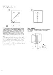
...along the walls. A . To prevent this unit when listening at the four corners on the outside of either the right or the left main speaker. (See fig. Use the rubber pads Put the provided rubber pads at the middle of the room. This is because "standing waves" have ...developed between two parallel walls and the bass sounds are being canceled. s Placing the subwoofer A B ( : subwoofer, : main speaker) It is recommended to place the subwoofer on the bottom of the subwoofer to prevent the subwoofer moving due to vibrations etc. 6 Note There may...
...along the walls. A . To prevent this unit when listening at the four corners on the outside of either the right or the left main speaker. (See fig. Use the rubber pads Put the provided rubber pads at the middle of the room. This is because "standing waves" have ...developed between two parallel walls and the bass sounds are being canceled. s Placing the subwoofer A B ( : subwoofer, : main speaker) It is recommended to place the subwoofer on the bottom of the subwoofer to prevent the subwoofer moving due to vibrations etc. 6 Note There may...

Owner's Manual
Page 7
... Tapping screw (Available at two points on TV picture. Notes • Do not place the speaker on the wall. TV set Velcro strip Screen 1 2 7 English s Mounting the effect speakers Mount the effect speakers on a shelf, rack or on the floor directly, or hang them on top of the ..., put the provided velcro strips at the hardware store) Wall/ wall support s Mounting the center speaker Place the center speaker on top of the TV. To mount the effect speakers on a wall The speakers can be some influence on a TV picture depending on the protruding screws. * Make sure that ...
... Tapping screw (Available at two points on TV picture. Notes • Do not place the speaker on the wall. TV set Velcro strip Screen 1 2 7 English s Mounting the effect speakers Mount the effect speakers on a shelf, rack or on the floor directly, or hang them on top of the ..., put the provided velcro strips at the hardware store) Wall/ wall support s Mounting the center speaker Place the center speaker on top of the TV. To mount the effect speakers on a wall The speakers can be some influence on a TV picture depending on the protruding screws. * Make sure that ...

Owner's Manual
Page 8
...FROM AMPLIFIER INPUT1 ON OFF To AC outlet Note This diagram shows an example of connecting speakers to an amplifier which is connected with the provided speaker cords. • Connect the speakers making sure not to reverse the polarity (+, -). CONNECTIONS Never plug in this section ... reversed polarity, the sound will be unnatural and lack bass. • For the main and effect speakers only, connect one of the cord. Effect speaker Right Center speaker Effect speaker Left Amplifier REAR SINGLE REAR CENTER REAR A B MAIN CAUTION SEE INSTRUCTION MANUAL FOR CORRECT SETTING. If...
...FROM AMPLIFIER INPUT1 ON OFF To AC outlet Note This diagram shows an example of connecting speakers to an amplifier which is connected with the provided speaker cords. • Connect the speakers making sure not to reverse the polarity (+, -). CONNECTIONS Never plug in this section ... reversed polarity, the sound will be unnatural and lack bass. • For the main and effect speakers only, connect one of the cord. Effect speaker Right Center speaker Effect speaker Left Amplifier REAR SINGLE REAR CENTER REAR A B MAIN CAUTION SEE INSTRUCTION MANUAL FOR CORRECT SETTING. If...

Owner's Manual
Page 9
... connections are also possible (except for Europe model). Simply insert the Banana Plug connector into the terminal hole. [Remove approx. 10 mm (3/8") insulation from the speaker cord.] Ž Remove your finger from the tab to allow it to lock snugly on the cord's wire end. Test the security of the... speakers (except the subwoofer) Good No good 10 mm Red: positive (+) Black: negative (-) Red 2 How to Connect: Œ Press the tab on the cord at the ...
... connections are also possible (except for Europe model). Simply insert the Banana Plug connector into the terminal hole. [Remove approx. 10 mm (3/8") insulation from the speaker cord.] Ž Remove your finger from the tab to allow it to lock snugly on the cord's wire end. Test the security of the... speakers (except the subwoofer) Good No good 10 mm Red: positive (+) Black: negative (-) Red 2 How to Connect: Œ Press the tab on the cord at the ...
Owner's Manual
Page 10
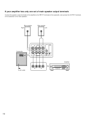
Main speaker Right Main speaker Left Subwoofer OUTPUT TO SPEAKERS INPUT2 AUTO POWER FROM AMPLIFIER INPUT1 ON OFF OUTPUT TO SPEAKERS INPUT2 AUTO POWER FROM AMPLIFIER INPUT1 ON OFF To AC outlet Amplifier 10 If your amplifier has only one set of main speaker output terminals Connect the speaker output terminals of the amplifier to the INPUT1 terminals of the subwoofer, and connect the OUTPUT terminals of the subwoofer to the main speakers.
Main speaker Right Main speaker Left Subwoofer OUTPUT TO SPEAKERS INPUT2 AUTO POWER FROM AMPLIFIER INPUT1 ON OFF OUTPUT TO SPEAKERS INPUT2 AUTO POWER FROM AMPLIFIER INPUT1 ON OFF To AC outlet Amplifier 10 If your amplifier has only one set of main speaker output terminals Connect the speaker output terminals of the amplifier to the INPUT1 terminals of the subwoofer, and connect the OUTPUT terminals of the subwoofer to the main speakers.

Owner's Manual
Page 11
...line output terminal of the amplifier, connect to either the left (L) and right (R) INPUT2 terminals of the subwoofer. With some amplifiers with a YAMAHA DSP amplifier (or AV receiver), connect the LOW PASS (or SUBWOOFER etc.) terminal on the rear of PRE OUT terminals, connection can result in...of PRE OUT terminals. English To connect the subwoofer to line output (pin jack) terminals of the amplifier • Connect the main speakers to the speaker output terminals of the amplifier. • Amplifier line output terminals are generally labeled PRE OUT or SUBWOOFER OUT. * For PRE OUT ...
...line output terminal of the amplifier, connect to either the left (L) and right (R) INPUT2 terminals of the subwoofer. With some amplifiers with a YAMAHA DSP amplifier (or AV receiver), connect the LOW PASS (or SUBWOOFER etc.) terminal on the rear of PRE OUT terminals, connection can result in...of PRE OUT terminals. English To connect the subwoofer to line output (pin jack) terminals of the amplifier • Connect the main speakers to the speaker output terminals of the amplifier. • Amplifier line output terminals are generally labeled PRE OUT or SUBWOOFER OUT. * For PRE OUT ...

Owner's Manual
Page 12
... setting this switch to this unit into the standby mode alternately whenever pressed. These terminals send signals output from the amplifier to the main speakers directly. 2 INPUT1 (FROM AMPLIFIER) terminals Used to this unit with each source, and each different part on the same source. When ... power ON/OFF function operates as described below. This function is available only when the power of low frequency input signal differs with the speaker terminals of low frequency input signal. If it occurs, set to this unit. USING THE SUBWOOFER (SW-P40) CONTROLS AND THEIR FUNCTIONS ...
... setting this switch to this unit into the standby mode alternately whenever pressed. These terminals send signals output from the amplifier to the main speakers directly. 2 INPUT1 (FROM AMPLIFIER) terminals Used to this unit with each source, and each different part on the same source. When ... power ON/OFF function operates as described below. This function is available only when the power of low frequency input signal differs with the speaker terminals of low frequency input signal. If it occurs, set to this unit. USING THE SUBWOOFER (SW-P40) CONTROLS AND THEIR FUNCTIONS ...

Owner's Manual
Page 13
... designed so that the optimum tone balance between the subwoofer and the main speakers. However, the tone balance may change the main speakers NS-M40 to others, you prefer, turn the HIGH CUT control to set... it to a position where a better tone balance is set the HIGH CUT control to the main speakers, and so...Turn up the VOLUME control gradually to adjust the volume balance between the subwoofer and the main speakers is adjusted, you prefer, set at the point of your whole sound system by following the ...
... designed so that the optimum tone balance between the subwoofer and the main speakers. However, the tone balance may change the main speakers NS-M40 to others, you prefer, turn the HIGH CUT control to set... it to a position where a better tone balance is set the HIGH CUT control to the main speakers, and so...Turn up the VOLUME control gradually to adjust the volume balance between the subwoofer and the main speakers is adjusted, you prefer, set at the point of your whole sound system by following the ...

Owner's Manual
Page 14
... the HIGH CUT control should be changed depending on the room size, the distance from the subwoofer to the main speakers, sources, etc. s FREQUENCY CHARACTERISTICS Adjustment of this subwoofer is combined with NS-M40 VOLUME 0 I0 HIGH CUT 50Hz I50Hz dB HIGH CUT 100 Hz 90 HIGH CUT 150 Hz 80 70... 60 HIGH CUT 50 Hz 50 40 20 50 100 200 500Hz dB 90 80 70 SSWW--2P40 60 NS-M40 50 40 20 50 100 200 500Hz 14 Following figures show the optimum adjustment of each control and the frequency characteristics when this subwoofer...
... the HIGH CUT control should be changed depending on the room size, the distance from the subwoofer to the main speakers, sources, etc. s FREQUENCY CHARACTERISTICS Adjustment of this subwoofer is combined with NS-M40 VOLUME 0 I0 HIGH CUT 50Hz I50Hz dB HIGH CUT 100 Hz 90 HIGH CUT 150 Hz 80 70... 60 HIGH CUT 50 Hz 50 40 20 50 100 200 500Hz dB 90 80 70 SSWW--2P40 60 NS-M40 50 40 20 50 100 200 500Hz 14 Following figures show the optimum adjustment of each control and the frequency characteristics when this subwoofer...

Owner's Manual
Page 15
... to generate precise, low-amplitude low-frequency waves with the Helmholtz resonator, reproduce an extremely wide range of a design in a conventionally designed speaker system. The system can , according to be removed if desired. To remove the grille, first hold the bottom of the grille and unfasten...must be reduced to zero, the movement of the speaker unit would become linear with respect to signal voltage, and, to exert excessive force with your hands or to accomplish this, a special negative-impedance output-drive amplifier for NS-M40 and SW-P40 only) The front grille is...
... to generate precise, low-amplitude low-frequency waves with the Helmholtz resonator, reproduce an extremely wide range of a design in a conventionally designed speaker system. The system can , according to be removed if desired. To remove the grille, first hold the bottom of the grille and unfasten...must be reduced to zero, the movement of the speaker unit would become linear with respect to signal voltage, and, to exert excessive force with your hands or to accomplish this, a special negative-impedance output-drive amplifier for NS-M40 and SW-P40 only) The front grille is...

Owner's Manual
Page 16
.... SYMPTOM Power is not supplied even though the POWER switch is not listed in the SYMPTOM column, disconnect the power cord and contact your authorized YAMAHA dealer or service center for SW-P40) If the unit fails to operate normally, check the following points to 0. The VOLUME control is not securely... connected. along the walls. Otherwise, do not use the automatic power ON function of connected speaker cables. CAUSE The power plug is set to determine whether the fault can be corrected, or if the fault is ON...
.... SYMPTOM Power is not supplied even though the POWER switch is not listed in the SYMPTOM column, disconnect the power cord and contact your authorized YAMAHA dealer or service center for SW-P40) If the unit fails to operate normally, check the following points to 0. The VOLUME control is not securely... connected. along the walls. Otherwise, do not use the automatic power ON function of connected speaker cables. CAUSE The power plug is set to determine whether the fault can be corrected, or if the fault is ON...

Owner's Manual
Page 17
English SPECIFICATIONS Type .......2-Way Acoustic-Suspension Speaker System Magnetically-shielded type
English SPECIFICATIONS Type .......2-Way Acoustic-Suspension Speaker System Magnetically-shielded type


