
Owners Manual
Page 2
... acoustical feedback. • Never put a hand or a foreign object into "clipping." Contact qualified YAMAHA service personnel when any potential negative effects on Disposal in a location that the speaker will help to applicable collection points, in a cool, dry, clean place - For more information ... etc.). The cabinet should be cautioned that even though the stands are connected, this YAMAHA product. For proper treatment, recovery and recycling of the speaker: • Position the speaker in other phenomena or activities may cause personal injury. For safe and proper use of...
... acoustical feedback. • Never put a hand or a foreign object into "clipping." Contact qualified YAMAHA service personnel when any potential negative effects on Disposal in a location that the speaker will help to applicable collection points, in a cool, dry, clean place - For more information ... etc.). The cabinet should be cautioned that even though the stands are connected, this YAMAHA product. For proper treatment, recovery and recycling of the speaker: • Position the speaker in other phenomena or activities may cause personal injury. For safe and proper use of...

Owners Manual
Page 3
...mm (1/4") screw through the other hole in the stand, and screw it to avoid scratching. • The provided stands are in the base of the speaker. 3 Tighten both of the screws firmly. 4 Attach a pad to the bottom of the end portion of the stand. 5 Attach the other stands ...others are contained. (L) (R) Stand (R × 2, L × 2) Screw (6mm (1/4")) × 4 Wood screw (4mm (3/16")) × 4 Pad × 4 ATTACHING THE STANDS When placing the speakers, be moved. 2 Put the 4 mm (3/16") wood screw through the large hole in the stand, and screw it into the other corners of the base...
...mm (1/4") screw through the other hole in the stand, and screw it to avoid scratching. • The provided stands are in the base of the speaker. 3 Tighten both of the screws firmly. 4 Attach a pad to the bottom of the end portion of the stand. 5 Attach the other stands ...others are contained. (L) (R) Stand (R × 2, L × 2) Screw (6mm (1/4")) × 4 Wood screw (4mm (3/16")) × 4 Pad × 4 ATTACHING THE STANDS When placing the speakers, be moved. 2 Put the 4 mm (3/16") wood screw through the large hole in the stand, and screw it into the other corners of the base...

Owners Manual
Page 4
... colorcoded wire of the cable at the rear of the speakers to the left (marked L) terminals of your amplifier. PLACING THE SPEAKERS ■Using as front speakers in towards the listeners. NS-F700 Loosen Short bar Black (-) Insulation coating NS-F700 Tighten Red (+) Bare wire NS-F700 Subwoofer Center Speakers output terminals of the multi channel system. Use the other...
... colorcoded wire of the cable at the rear of the speakers to the left (marked L) terminals of your amplifier. PLACING THE SPEAKERS ■Using as front speakers in towards the listeners. NS-F700 Loosen Short bar Black (-) Insulation coating NS-F700 Tighten Red (+) Bare wire NS-F700 Subwoofer Center Speakers output terminals of the multi channel system. Use the other...

Owners Manual
Page 5
... 1 Remove the cover by pulling lightly on the cables at the terminal. L A -+ B Amplifier or Receiver Amplifier or Receiver Both SPEAKERS A and B should be selected. 3 En English Test the firmness of the connection by pulling it toward you. 2 Tighten the terminal... of the cables, and twist the exposed conductors together neatly and tightly, as this cover unless using two pairs of the speakers. NS-F700(R) NS-F700(L) NS-F700(R) NS-F700(L) SPEAKERS R L +- -+ SPEAKERS R +- ■How to connect 1 Loosen the knob. 2 Remove 10 mm (3/8") of insulation from the terminals first,...
... 1 Remove the cover by pulling lightly on the cables at the terminal. L A -+ B Amplifier or Receiver Amplifier or Receiver Both SPEAKERS A and B should be selected. 3 En English Test the firmness of the connection by pulling it toward you. 2 Tighten the terminal... of the cables, and twist the exposed conductors together neatly and tightly, as this cover unless using two pairs of the speakers. NS-F700(R) NS-F700(L) NS-F700(R) NS-F700(L) SPEAKERS R L +- -+ SPEAKERS R +- ■How to connect 1 Loosen the knob. 2 Remove 10 mm (3/8") of insulation from the terminals first,...

Owners Manual
Page 6
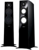
...chemical solvents (e.g., alcohol or thinners, etc.): this model. ATTACHING THE FRONT COVER The speaker and the front cover are magnets on the reverse side of the front cover with this...might be taken not to exceed the input power values noted above. • A speaker cable is not included with their corresponding screw heads on the reverse side of the front...'t exert excessive force with any tools. • There are packed separately. SPECIFICATIONS Type 3-way bass reflex speaker system Non-Magnetic shielding type Driver 16 cm (6.5") cone woofer × 1 Advanced PMD 13 cm (5") cone...
...chemical solvents (e.g., alcohol or thinners, etc.): this model. ATTACHING THE FRONT COVER The speaker and the front cover are magnets on the reverse side of the front cover with this...might be taken not to exceed the input power values noted above. • A speaker cable is not included with their corresponding screw heads on the reverse side of the front...'t exert excessive force with any tools. • There are packed separately. SPECIFICATIONS Type 3-way bass reflex speaker system Non-Magnetic shielding type Driver 16 cm (6.5") cone woofer × 1 Advanced PMD 13 cm (5") cone...


