Owners Manual
Page 1
A II A NS-AW190/NS-AW390 INDOOR / OUTDOOR SPEAKER SYSTEM I Ilf CONTENTS CONSUMER PRECAUTIONS 2 UNPACKING 3 MOUNTING THE SPEAKERS 4 CONNECTIONS TO YOUR AMPLIFIER 6 SETTING UP THE SPEAKERS 7 SPECIFICATIONS 8 OWNER'S MANUAL
A II A NS-AW190/NS-AW390 INDOOR / OUTDOOR SPEAKER SYSTEM I Ilf CONTENTS CONSUMER PRECAUTIONS 2 UNPACKING 3 MOUNTING THE SPEAKERS 4 CONNECTIONS TO YOUR AMPLIFIER 6 SETTING UP THE SPEAKERS 7 SPECIFICATIONS 8 OWNER'S MANUAL
Owners Manual
Page 2
To clean wipe with nails, adhesives, or other unsafe hardware. YAMAHA shall not be damaged, or result in corners or under eaves. • Since these speakers are to thin plywood or soft wall surface materials as this might damage the finish. CONSUMER PRECAUTIONS Read these .... • Do not attach them to be driven into "clipping". • Do not attempt to clean the speakers with your NS-AW190/NS-AW390 speakers. • When installing these speakers outdoors, try to minimize their exposure to excessive physical shock. If they are dented or bent, the sound will ...
To clean wipe with nails, adhesives, or other unsafe hardware. YAMAHA shall not be damaged, or result in corners or under eaves. • Since these speakers are to thin plywood or soft wall surface materials as this might damage the finish. CONSUMER PRECAUTIONS Read these .... • Do not attach them to be driven into "clipping". • Do not attempt to clean the speakers with your NS-AW190/NS-AW390 speakers. • When installing these speakers outdoors, try to minimize their exposure to excessive physical shock. If they are dented or bent, the sound will ...
Owners Manual
Page 3
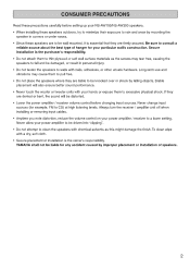
Speaker x 2 Large bracket screw x 4 Screw for safety wire x 2 _______, i --------- ( AD) %O ----i - t,i. - Mounting bracket x 2 Safety wire x 2 .---- - O 0 3 UNPACKING After unpacking, please inspect contents to confirm all the following items are contained.
Speaker x 2 Large bracket screw x 4 Screw for safety wire x 2 _______, i --------- ( AD) %O ----i - t,i. - Mounting bracket x 2 Safety wire x 2 .---- - O 0 3 UNPACKING After unpacking, please inspect contents to confirm all the following items are contained.
Owners Manual
Page 4
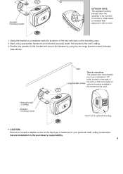
...• 0 C Supplied mounting bracket OUTDOOR NOTE: The supplied mounting I brackets allow the speakers to be used. 114 • • Insert nut for optional mounting. * CAUTION:...the key hole slots on the mounting area. 2. Secure installation is the purchaser's responsibility. 4 Position the speaker in corners or under eaves to minimize their exposure to wall or ceiling Supplied mounting bracket Wall Tips for ...the market can be mounted in the bracket and secure the speaker by using appropriate hardware (not included) securely fasten the bracket to the wall / ceiling. 3.
...• 0 C Supplied mounting bracket OUTDOOR NOTE: The supplied mounting I brackets allow the speakers to be used. 114 • • Insert nut for optional mounting. * CAUTION:...the key hole slots on the mounting area. 2. Secure installation is the purchaser's responsibility. 4 Position the speaker in corners or under eaves to minimize their exposure to wall or ceiling Supplied mounting bracket Wall Tips for ...the market can be mounted in the bracket and secure the speaker by using appropriate hardware (not included) securely fasten the bracket to the wall / ceiling. 3.
Owners Manual
Page 5
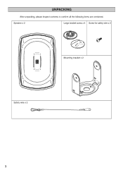
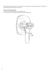
When using speaker brackets to mount the speaker on a wall, please use safety wire between the speaker and the bracket to use the safety wire: 1. Hook one side of the safety wire together with the supplied screw. 5 Fix the other side of the safety wire to the bracket's hole. 2. How to prevent the speaker from falling.
When using speaker brackets to mount the speaker on a wall, please use safety wire between the speaker and the bracket to use the safety wire: 1. Hook one side of the safety wire together with the supplied screw. 5 Fix the other side of the safety wire to the bracket's hole. 2. How to prevent the speaker from falling.
Owners Manual
Page 6
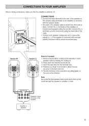
... to lock securely on the bare wire end. ® Test the firmness of the connection by pulling lightly on both . Speaker (R) er\ v se3 Speaker (L) How to Connect CI Remove the insulation coating at the extremity of each other side is connected with reversed polarity, the... is red and the other as this could damage the speaker or amplifier, or both components using the red side. SPEAKERS RI IL + - * * Speakers output terminals of the amplifier Amplifier or Receiver 6 Note Do not let the bare speaker wires touch each speaker cable by twisting the coating off . Aro I I e (w)) ...
... to lock securely on the bare wire end. ® Test the firmness of the connection by pulling lightly on both . Speaker (R) er\ v se3 Speaker (L) How to Connect CI Remove the insulation coating at the extremity of each other side is connected with reversed polarity, the... is red and the other as this could damage the speaker or amplifier, or both components using the red side. SPEAKERS RI IL + - * * Speakers output terminals of the amplifier Amplifier or Receiver 6 Note Do not let the bare speaker wires touch each speaker cable by twisting the coating off . Aro I I e (w)) ...
Owners Manual
Page 7
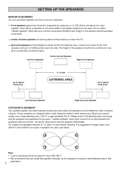
..."middle-omission" effect (lack of sound in an area between 6'-10' apart for every 200-400 ft. • We recommend that protect the speakers form the elements when mounted outdoors. It is suggested for larger areas (over a large listening area. (100 ft2 to 2 additional feet apart per... side. Left Front Speaker Center channel Speaker Right Front Speaker up to approx 2 feet more 6-10 feet LISTENIANRGEt 1 up to approximately 400 ft2). Conversely, If placed too far apart, the so...
..."middle-omission" effect (lack of sound in an area between 6'-10' apart for every 200-400 ft. • We recommend that protect the speakers form the elements when mounted outdoors. It is suggested for larger areas (over a large listening area. (100 ft2 to 2 additional feet apart per... side. Left Front Speaker Center channel Speaker Right Front Speaker up to approx 2 feet more 6-10 feet LISTENIANRGEt 1 up to approximately 400 ft2). Conversely, If placed too far apart, the so...
Owners Manual
Page 8
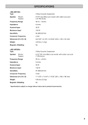
... Dome 65 Hz - 40 kHz 6 ohms 35 W 120 W 85 dB/2.83 V/m 4 kHz 8-27/32" x 5-7/8" x 5-19/32" (225 x 149 x 142 mm) 3.09 lbs (1.4 kg) No Type Speaker Woofer Tweeter Frequency Range Impedance Nominal Input Maximum Input Sensitivity Crossover Frequency Dimension (H x W x D) Weight Magnetic Shielding 2-Way Acoustic Suspension 6-1/2" P.P. SPECIFICATIONS Type...
... Dome 65 Hz - 40 kHz 6 ohms 35 W 120 W 85 dB/2.83 V/m 4 kHz 8-27/32" x 5-7/8" x 5-19/32" (225 x 149 x 142 mm) 3.09 lbs (1.4 kg) No Type Speaker Woofer Tweeter Frequency Range Impedance Nominal Input Maximum Input Sensitivity Crossover Frequency Dimension (H x W x D) Weight Magnetic Shielding 2-Way Acoustic Suspension 6-1/2" P.P. SPECIFICATIONS Type...
Owners Manual
Page 9
LIMITED WARRANTY INDOOR / OUTDOOR SPEAKER SYSTEM Duration of Warranty: This Speaker System is enforceable only by YAMAHA, please contact YAMAHA's Service Department. (5) Any unit used for industrial or commercial purposes. This warranty covers all defects in...U.S.A. (2) Units shipped for and what you can get Warranty Service: (1) YAMAHA Speaker Systems requiring service must pay the return shipping charges to follow instructions contained in your authorized Yamaha dealer or the Yamaha Electronics Corporation, USA, service department if you need assistance in the U.S.A. ...
LIMITED WARRANTY INDOOR / OUTDOOR SPEAKER SYSTEM Duration of Warranty: This Speaker System is enforceable only by YAMAHA, please contact YAMAHA's Service Department. (5) Any unit used for industrial or commercial purposes. This warranty covers all defects in...U.S.A. (2) Units shipped for and what you can get Warranty Service: (1) YAMAHA Speaker Systems requiring service must pay the return shipping charges to follow instructions contained in your authorized Yamaha dealer or the Yamaha Electronics Corporation, USA, service department if you need assistance in the U.S.A. ...


