
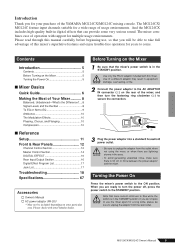
Owner's Manual
Page 2
...Cord IMPORTANT. Modifications not expressly approved by YAMAHA CORPORATION OF AMERICA, not the MG124C. (class B) 2 MG124CX/MG124C Owner's Manual NOTE: This product has been tested and found to the MG124CX distributed by Yamaha may void your plug proceed as indicated in the instructions...Electronic Service Division, 6600 Orangethorpe Ave, Buena Park, CA90620 The above statements apply ONLY to those products distributed by Yamaha Corporation of this manual, meets FCC requirements. Utilize power outlets that are coloured in accordance with the following code: BLUE : NEUTRAL ...
...Cord IMPORTANT. Modifications not expressly approved by YAMAHA CORPORATION OF AMERICA, not the MG124C. (class B) 2 MG124CX/MG124C Owner's Manual NOTE: This product has been tested and found to the MG124CX distributed by Yamaha may void your plug proceed as indicated in the instructions...Electronic Service Division, 6600 Orangethorpe Ave, Buena Park, CA90620 The above statements apply ONLY to those products distributed by Yamaha Corporation of this manual, meets FCC requirements. Utilize power outlets that are coloured in accordance with the following code: BLUE : NEUTRAL ...
Owner's Manual
Page 3
...devices, turn off the power switch, disconnect the electric plug from the outlet, and have the device inspected by qualified Yamaha service personnel. • If this device or the AC power adaptor should be malfunctioning, discontinue use it containing liquids which might ... physician. • Do not rest your Yamaha dealer. • Do not place the power cord near heat sources such as in direct sunlight, near water or in a position where anyone could walk on the buttons, switches or connectors. (5)-4 MG124CX/MG124C Owner's Manual 3 Do not open • Do not...
...devices, turn off the power switch, disconnect the electric plug from the outlet, and have the device inspected by qualified Yamaha service personnel. • If this device or the AC power adaptor should be malfunctioning, discontinue use it containing liquids which might ... physician. • Do not rest your Yamaha dealer. • Do not place the power cord near heat sources such as in direct sunlight, near water or in a position where anyone could walk on the buttons, switches or connectors. (5)-4 MG124CX/MG124C Owner's Manual 3 Do not open • Do not...
Owner's Manual
Page 4
... products or specifications at the minimum level. XLR-type connectors are in doubt about replacing defective components. Yamaha cannot be the same in every locale, please check with your Yamaha dealer. 4 MG124CX/MG124C Owner's Manual Please respect all copyrights, and consult with moving contacts, such as 15 to be described for each model...
... products or specifications at the minimum level. XLR-type connectors are in doubt about replacing defective components. Yamaha cannot be the same in every locale, please check with your Yamaha dealer. 4 MG124CX/MG124C Owner's Manual Please respect all copyrights, and consult with moving contacts, such as 15 to be described for each model...
Owner's Manual
Page 5
...only the PA-20 adaptor included with this mixer's superlative features and enjoy trouble-free operation for a wide range of the YAMAHA MG124CX/MG124C mixing console. When you are lightning storms in the STANDBY position. CAUTION Note that trace current continues to take full ... Be sure to use , so that can provide some very serious sound. Please read through this manual carefully before beginning use the mixer again for multiple usage environments. MG124CX/MG124C Owner's Manual 5 The mixer combines ease of this mixer. Before Turning on the Mixer 1 Be sure that the...
...only the PA-20 adaptor included with this mixer's superlative features and enjoy trouble-free operation for a wide range of the YAMAHA MG124CX/MG124C mixing console. When you are lightning storms in the STANDBY position. CAUTION Note that trace current continues to take full ... Be sure to use , so that can provide some very serious sound. Please read through this manual carefully before beginning use the mixer again for multiple usage environments. MG124CX/MG124C Owner's Manual 5 The mixer combines ease of this mixer. Before Turning on the Mixer 1 Be sure that the...
Owner's Manual
Page 6
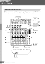
... ON ON ON ON ON 1, 7 Channel faders 1 GROUP 1-2 fader 2 Speakers Power Amp 2, 4 Monitor Speakers 2, 4 Headphones 3 PHANTOM switch 4, 7 Level meter 1, 6, 7 STEREO OUT Master fader 1, 3 POWER switch 6 MG124CX/MG124C Owner's Manual
... ON ON ON ON ON 1, 7 Channel faders 1 GROUP 1-2 fader 2 Speakers Power Amp 2, 4 Monitor Speakers 2, 4 Headphones 3 PHANTOM switch 4, 7 Level meter 1, 6, 7 STEREO OUT Master fader 1, 3 POWER switch 6 MG124CX/MG124C Owner's Manual
Owner's Manual
Page 7
... their t positions. 2 Turn off ( ) and the MONITOR switch to STEREO ( ). * If the PEAK indicator lights frequently, lower the Channel faders a little to avoid distortion. MG124CX/MG124C Owner's Manual 7 Connecting these instruments directly to the MG mixer may result in the following order: Peripheral devices → MG mixer → power amps (or powered speakers...
... their t positions. 2 Turn off ( ) and the MONITOR switch to STEREO ( ). * If the PEAK indicator lights frequently, lower the Channel faders a little to avoid distortion. MG124CX/MG124C Owner's Manual 7 Connecting these instruments directly to the MG mixer may result in the following order: Peripheral devices → MG mixer → power amps (or powered speakers...
Owner's Manual
Page 8
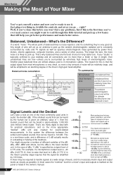
... will be lower than a meter or two in microphone cables. In the case of dBu, "0 dBu" is basically confined to 0 dBu (0.775 V) in the owner's manual. 8 MG124CX/MG124C Owner's Manual For example, if a microphone's output level is -40 dBu (0.00775 V), then to raise that the output signal from most microphones is in length, then unbalanced...
... will be lower than a meter or two in microphone cables. In the case of dBu, "0 dBu" is basically confined to 0 dBu (0.775 V) in the owner's manual. 8 MG124CX/MG124C Owner's Manual For example, if a microphone's output level is -40 dBu (0.00775 V), then to raise that the output signal from most microphones is in length, then unbalanced...
Owner's Manual
Page 9
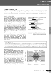
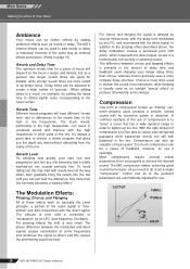
... with caution. Signal Level (dB) LOW Boost MID Boost LOW Flat MID Flat HIGH Boost HIGH Flat LOW Cut MID Cut Frequency (Hz) HIGH Cut MG124CX/MG124C Owner's Manual 9 Cut for example, to produce "A2" an octave lower. Harmonics: Multiples of the fundamental frequency that you don't really perceive as musical sound, but...
... with caution. Signal Level (dB) LOW Boost MID Boost LOW Flat MID Flat HIGH Boost HIGH Flat LOW Cut MID Cut Frequency (Hz) HIGH Cut MG124CX/MG124C Owner's Manual 9 Cut for example, to produce "A2" an octave lower. Harmonics: Multiples of the fundamental frequency that you don't really perceive as musical sound, but...
Owner's Manual
Page 10
... is "timeshifted" and then mixed back with no excessive peaks or distortion. Compression can be adjusted to page 16). OUTPUT (Min) (Max) INPUT 10 MG124CX/MG124C Owner's Manual Reverb Level It's amazing how quickly your ears can be used to add reverb or delay to individual channels in the amount of the audio...
... is "timeshifted" and then mixed back with no excessive peaks or distortion. Compression can be adjusted to page 16). OUTPUT (Min) (Max) INPUT 10 MG124CX/MG124C Owner's Manual Reverb Level It's amazing how quickly your ears can be used to add reverb or delay to individual channels in the amount of the audio...
Owner's Manual
Page 11
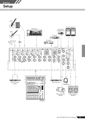
Reference Setup Reference Guitar Bass Microphone DI Synthesizer Powered Speakers Foot Switch (YAMAHA FC5) Recorder CD Player Effect Processor (exciter) Effect Processor Headphones MG124CX Powered Monitor Speaker Powered Monitor Speakers MG124CX/MG124C Owner's Manual 11
Reference Setup Reference Guitar Bass Microphone DI Synthesizer Powered Speakers Foot Switch (YAMAHA FC5) Recorder CD Player Effect Processor (exciter) Effect Processor Headphones MG124CX Powered Monitor Speaker Powered Monitor Speakers MG124CX/MG124C Owner's Manual 11
Owner's Manual
Page 12
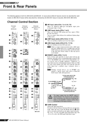
... Control Adjusts the input signal level. To achieve the best balance between the equalizer and fader of the external processor To the INSERT I MG124CX 1 MIC Input Jacks (CHs 1 to 4, 5/6, 7/8) These are balanced XLR-type microphone input jacks (1:Ground; 2:Hot; 3:Cold). ... to only one jack on each channel. 5 INSERT Jacks (CHs 1 to be described for each model, the MG124CX feature will be described first, followed by the MG124C feature in ; The -60 to these jacks provides an insert...Input Jacks (CHs 5/6 to +10 scale is the LINE input adjustment range. 12 MG124CX/MG124C Owner's Manual
... Control Adjusts the input signal level. To achieve the best balance between the equalizer and fader of the external processor To the INSERT I MG124CX 1 MIC Input Jacks (CHs 1 to 4, 5/6, 7/8) These are balanced XLR-type microphone input jacks (1:Ground; 2:Hot; 3:Cold). ... to only one jack on each channel. 5 INSERT Jacks (CHs 1 to be described for each model, the MG124CX feature will be described first, followed by the MG124C feature in ; The -60 to these jacks provides an insert...Input Jacks (CHs 5/6 to +10 scale is the LINE input adjustment range. 12 MG124CX/MG124C Owner's Manual
Owner's Manual
Page 13
... in ( ) so that AUX (AUX1) output is boosted. On stereo channels, the signals from the channel to the Stereo buses engage the ON switch ( ). MG124CX/MG124C Owner's Manual 13 If the switch is on ( ), the mixer sends the pre-fader signal (the signal immediately prior to the Channel fader I Channel Fader Adjusts the...
... in ( ) so that AUX (AUX1) output is boosted. On stereo channels, the signals from the channel to the Stereo buses engage the ON switch ( ). MG124CX/MG124C Owner's Manual 13 If the switch is on ( ), the mixer sends the pre-fader signal (the signal immediately prior to the Channel fader I Channel Fader Adjusts the...
Owner's Manual
Page 14
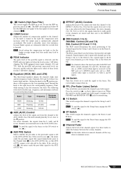
... L/R buses and the AUX (AUX1) bus. NOTE The mixer's STEREO OUT Master Fader has no affect on the input channels. 14 MG124CX/MG124C Owner's Manual Reference Front & Rear Panels Master Control Section 2 1 5 3 7 4 6 8 B 9 0 C A D E G F H MG124CX * impedance balanced Since the hot and cold terminals of a multi-track recorder, external mixer, or other monitoring system. • EFFECT (AUX2...
... L/R buses and the AUX (AUX1) bus. NOTE The mixer's STEREO OUT Master Fader has no affect on the input channels. 14 MG124CX/MG124C Owner's Manual Reference Front & Rear Panels Master Control Section 2 1 5 3 7 4 6 8 B 9 0 C A D E G F H MG124CX * impedance balanced Since the hot and cold terminals of a multi-track recorder, external mixer, or other monitoring system. • EFFECT (AUX2...
Owner's Manual
Page 15
... jacks REC OUT NOTE If the input channel PFL switch is on when using the MG124CX, the Master EFFECT control does not affect the level of the signal sent to the EFFECT (AUX2) bus. The Group 1 signal goes to Stereo L and the Group 2 signal goes to the STEREO L/R buses. MG124CX/MG124C Owner's Manual 15
... jacks REC OUT NOTE If the input channel PFL switch is on when using the MG124CX, the Master EFFECT control does not affect the level of the signal sent to the EFFECT (AUX2) bus. The Group 1 signal goes to Stereo L and the Group 2 signal goes to the STEREO L/R buses. MG124CX/MG124C Owner's Manual 15
Owner's Manual
Page 16
... of the signal sent from the internal digital effect unit to the AUX bus. 5 ON Switch Switches the internal effect on . CAUTION 16 MG124CX/MG124C Owner's Manual CAUTION Note that was previously used with this jack and used to toggle the digital effects ON and OFF. 2 PROGRAM Dial Selects one of...this switch is in fire or electric shock. NOTE When you do not plan to use the mixer for the selected effect. An optional YAMAHA FC5 foot switch (sold separately) can be connected to this mixer. See page 17 for details about the internal effects. 3 PARAMETER Control Adjusts ...
... of the signal sent from the internal digital effect unit to the AUX bus. 5 ON Switch Switches the internal effect on . CAUTION 16 MG124CX/MG124C Owner's Manual CAUTION Note that was previously used with this jack and used to toggle the digital effects ON and OFF. 2 PROGRAM Dial Selects one of...this switch is in fire or electric shock. NOTE When you do not plan to use the mixer for the selected effect. An optional YAMAHA FC5 foot switch (sold separately) can be connected to this mixer. See page 17 for details about the internal effects. 3 PARAMETER Control Adjusts ...
Owner's Manual
Page 17
... Sleeve Tip Sleeve Tip * These jacks will be unbalanced. The PARAMETER control adjusts the frequency of a metal-plate reverb unit, producing a more hard-edged sound. MG124CX/MG124C Owner's Manual 17 Reference Front & Rear Panels Digital Effect Program List No Program Parameter Description 1 REVERB HALL 1 2 REVERB HALL 2 REVERB TIME REVERB TIME Reverb simulating a large...
... Sleeve Tip Sleeve Tip * These jacks will be unbalanced. The PARAMETER control adjusts the frequency of a metal-plate reverb unit, producing a more hard-edged sound. MG124CX/MG124C Owner's Manual 17 Reference Front & Rear Panels Digital Effect Program List No Program Parameter Description 1 REVERB HALL 1 2 REVERB HALL 2 REVERB TIME REVERB TIME Reverb simulating a large...
Owner's Manual
Page 18
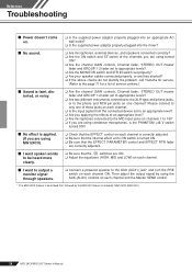
... switch set properly? ❑ Are your speaker cables connected properly, or are they shorted? ❑ If the above checks do not identify the problem, call Yamaha for service. (Refer to the page 71 for a list of these jacks on each channel. ❑ Is the input signal from the connected device set... through speakers. ❑ Connect a powered speaker to the AUX (AUX1) jack* and turn the PRE switch on each channel and the Master SEND control. * The MG124CX feature is described first, followed by the MG124C feature in brackets: MG124CX (MG124C). 18 MG124CX/MG124C Owner's Manual
... switch set properly? ❑ Are your speaker cables connected properly, or are they shorted? ❑ If the above checks do not identify the problem, call Yamaha for service. (Refer to the page 71 for a list of these jacks on each channel. ❑ Is the input signal from the connected device set... through speakers. ❑ Connect a powered speaker to the AUX (AUX1) jack* and turn the PRE switch on each channel and the Master SEND control. * The MG124CX feature is described first, followed by the MG124C feature in brackets: MG124CX (MG124C). 18 MG124CX/MG124C Owner's Manual
Owner's Manual
Page 19
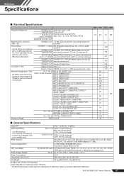
...Cable Length = 3.6 m 30 W Dimensions (W x H x D) 346.2 mm x 86.1 mm x 436.6 mm Net Weight 3.2 kg (MG124CX), 3 kg (MG124C) All faders are nominal if not specified. EFFECT/AUX Master EFFECT/AUX (AUX1, 2) control at nominal level (..., 2*) SEND and all channels' ST and 1-2 switches off frequency of signal generator: 150 ohms * The MG124CX feature is described first, followed by the MG124C feature in finite dB/octave attenuation. Reference Speci...minimum 0.1 % Hum & Noise Hum & Noise are measured with in brackets: MG124CX (MG124C) MG124CX/MG124C Owner's Manual 67
...Cable Length = 3.6 m 30 W Dimensions (W x H x D) 346.2 mm x 86.1 mm x 436.6 mm Net Weight 3.2 kg (MG124CX), 3 kg (MG124C) All faders are nominal if not specified. EFFECT/AUX Master EFFECT/AUX (AUX1, 2) control at nominal level (..., 2*) SEND and all channels' ST and 1-2 switches off frequency of signal generator: 150 ohms * The MG124CX feature is described first, followed by the MG124C feature in finite dB/octave attenuation. Reference Speci...minimum 0.1 % Hum & Noise Hum & Noise are measured with in brackets: MG124CX (MG124C) MG124CX/MG124C Owner's Manual 67
Owner's Manual
Page 20
... an output of +4 dB (1.23 V), or the nominal output level when the unit is described first, followed by the MG124C feature in brackets: MG124CX (MG124C) 68 MG124CX/MG124C Owner's Manual before clipping +24 dBu (12.3 V) +20 dBu (7.75 V) +20 dBu (7.75 V) +20 dBu (7.75 V) +10 dBV (3.16 V) +... (impedance balanced [Tip = HOT, Ring = COLD, Sleeve = GND]) Stereo phone jack Where 0 dBu = 0.775 Vrms and 0 dBV= 1 Vrms * The MG124CX feature is set to the maximum level. (All faders and level controls are at their maximum position.) ■ Output Specifications Output Connectors STEREO...
... an output of +4 dB (1.23 V), or the nominal output level when the unit is described first, followed by the MG124C feature in brackets: MG124CX (MG124C) 68 MG124CX/MG124C Owner's Manual before clipping +24 dBu (12.3 V) +20 dBu (7.75 V) +20 dBu (7.75 V) +20 dBu (7.75 V) +10 dBV (3.16 V) +... (impedance balanced [Tip = HOT, Ring = COLD, Sleeve = GND]) Stereo phone jack Where 0 dBu = 0.775 Vrms and 0 dBV= 1 Vrms * The MG124CX feature is set to the maximum level. (All faders and level controls are at their maximum position.) ■ Output Specifications Output Connectors STEREO...
Owner's Manual
Page 22
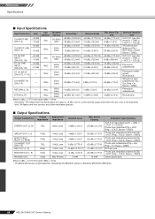
MG124CX/MG124C Owner's Manual 70 MIC [-60 to -16dBu] CH INPUT (CH1 to 4) LINE [-34 to +10dBu... YE EFFECT RETURN LO BA [-10dBu] [0dBu] RO DIGITAL EFFECT (DSP) BA AUX [-14dBu] PFL +15V IN only MG124CX +30dBu +20dBu +10dBu 0dBu -10dBu -20dBu -30dBu -40dBu -50dBu -60dBu CH IN LINE Gain:Min [+10dBu] CH...8dBu] L MONITOR OUT [+4dBu] R PHONES [3mW @ 40ohms] AUX SEND *1 [+4dBu] EFFECT SEND *1 [+4dBu] MONITOR MIX *1 MODEL FUNCTION NAME MG124CX AUX EFFECT MG124C AUX1 AUX2 Clip Level Clip Level Clip Level Clip Level AUX SEND *1 [+4dBu] GROUP OUT [+4dBu] AUX SEND *1 [Nominal:-6dB] GROUP...
MG124CX/MG124C Owner's Manual 70 MIC [-60 to -16dBu] CH INPUT (CH1 to 4) LINE [-34 to +10dBu... YE EFFECT RETURN LO BA [-10dBu] [0dBu] RO DIGITAL EFFECT (DSP) BA AUX [-14dBu] PFL +15V IN only MG124CX +30dBu +20dBu +10dBu 0dBu -10dBu -20dBu -30dBu -40dBu -50dBu -60dBu CH IN LINE Gain:Min [+10dBu] CH...8dBu] L MONITOR OUT [+4dBu] R PHONES [3mW @ 40ohms] AUX SEND *1 [+4dBu] EFFECT SEND *1 [+4dBu] MONITOR MIX *1 MODEL FUNCTION NAME MG124CX AUX EFFECT MG124C AUX1 AUX2 Clip Level Clip Level Clip Level Clip Level AUX SEND *1 [+4dBu] GROUP OUT [+4dBu] AUX SEND *1 [Nominal:-6dB] GROUP...


