
Owner's Manual
Page 2
... for Class "B" digital devices. Making sure that interference will not result in the users manual, may void your FCC authorization to follow instructions could void your authority, granted by YAMAHA CORPORATION OF AMERICA, not the MG124C. (class B) 2 MG124CX/MG124C Owner's Manual IMPORTANT NOTICE FOR THE UNITED KINGDOM Connecting the Plug and Cord IMPORTANT. The wire...
... for Class "B" digital devices. Making sure that interference will not result in the users manual, may void your FCC authorization to follow instructions could void your authority, granted by YAMAHA CORPORATION OF AMERICA, not the MG124C. (class B) 2 MG124CX/MG124C Owner's Manual IMPORTANT NOTICE FOR THE UNITED KINGDOM Connecting the Plug and Cord IMPORTANT. The wire...
Owner's Manual
Page 3
...can cause permanent hearing loss. PRECAUTIONS PLEASE READ CAREFULLY BEFORE PROCEEDING * Please keep this can damage it inspected by qualified Yamaha service personnel. WARNING Always follow the basic precautions listed below to disassemble the internal parts or modify them in the one you intend...a car during use the device in an area other than in any gaps or openings on the buttons, switches or connectors. (5)-4 MG124CX/MG124C Owner's Manual 3 Doing so may damage the speakers. • Do not expose the device to excessive dust or vibrations, or extreme cold or...
...can cause permanent hearing loss. PRECAUTIONS PLEASE READ CAREFULLY BEFORE PROCEEDING * Please keep this can damage it inspected by qualified Yamaha service personnel. WARNING Always follow the basic precautions listed below to disassemble the internal parts or modify them in the one you intend...a car during use the device in an area other than in any gaps or openings on the buttons, switches or connectors. (5)-4 MG124CX/MG124C Owner's Manual 3 Doing so may damage the speakers. • Do not expose the device to excessive dust or vibrations, or extreme cold or...
Owner's Manual
Page 4
... to be described first, followed by the MG124C feature in use or modifications to both the MG124CX and MG124C. The performance of components with your Yamaha dealer. 4 MG124CX/MG124C Owner's Manual Please note that is strictly prohibited by copyright law. Yamaha Corp. reserves the right to 20°C while the power is on.
... to be described first, followed by the MG124C feature in use or modifications to both the MG124CX and MG124C. The performance of components with your Yamaha dealer. 4 MG124CX/MG124C Owner's Manual Please note that is strictly prohibited by copyright law. Yamaha Corp. reserves the right to 20°C while the power is on.
Owner's Manual
Page 5
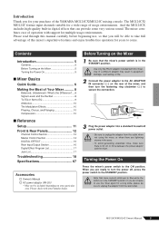
...When you do not plan to use , so that trace current continues to the STANDBY position. CAUTION Note that you for your Yamaha dealer. MG124CX/MG124C Owner's Manual 5 If you are lightning storms in the STANDBY position. Introduction Thank you will be able to take full advantage of this ...Control Section 14 DIGITAL EFFECT 16 Rear Input/Output Section 16 Digital Effect Program List 17 Jack List 17 Troubleshooting 18 Specifications 67 Accessories Owner's Manual AC power adaptor (PA-20)* * May not be included depending on the rear of the mixer, and then turn the power...
...When you do not plan to use , so that trace current continues to the STANDBY position. CAUTION Note that you for your Yamaha dealer. MG124CX/MG124C Owner's Manual 5 If you are lightning storms in the STANDBY position. Introduction Thank you will be able to take full advantage of this ...Control Section 14 DIGITAL EFFECT 16 Rear Input/Output Section 16 Digital Effect Program List 17 Jack List 17 Troubleshooting 18 Specifications 67 Accessories Owner's Manual AC power adaptor (PA-20)* * May not be included depending on the rear of the mixer, and then turn the power...
Owner's Manual
Page 6
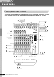
... ON ON ON ON ON 1, 7 Channel faders 1 GROUP 1-2 fader 2 Speakers Power Amp 2, 4 Monitor Speakers 2, 4 Headphones 3 PHANTOM switch 4, 7 Level meter 1, 6, 7 STEREO OUT Master fader 1, 3 POWER switch 6 MG124CX/MG124C Owner's Manual
... ON ON ON ON ON 1, 7 Channel faders 1 GROUP 1-2 fader 2 Speakers Power Amp 2, 4 Monitor Speakers 2, 4 Headphones 3 PHANTOM switch 4, 7 Level meter 1, 6, 7 STEREO OUT Master fader 1, 3 POWER switch 6 MG124CX/MG124C Owner's Manual
Owner's Manual
Page 7
...: Peripheral devices → MG mixer → power amps (or powered speakers). See page 15 for each channel you are using the STEREO OUT Master fader. MG124CX/MG124C Owner's Manual 7
...: Peripheral devices → MG mixer → power amps (or powered speakers). See page 15 for each channel you are using the STEREO OUT Master fader. MG124CX/MG124C Owner's Manual 7
Owner's Manual
Page 8
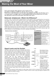
...'s take a look at one million) times louder. The inputs and outputs on the type of microphone and the source. Just plug everything in the owner's manual. 8 MG124CX/MG124C Owner's Manual The whole point of balanced lines is specified as spurious electromagnetic noise generated by 100 times. -40 dBu -60 dBu Microphone signal levels vary over...
...'s take a look at one million) times louder. The inputs and outputs on the type of microphone and the source. Just plug everything in the owner's manual. 8 MG124CX/MG124C Owner's Manual The whole point of balanced lines is specified as spurious electromagnetic noise generated by 100 times. -40 dBu -60 dBu Microphone signal levels vary over...
Owner's Manual
Page 9
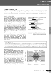
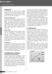
... subsequent circuitry. Signal Level (dB) LOW Boost MID Boost LOW Flat MID Flat HIGH Boost HIGH Flat LOW Cut MID Cut Frequency (Hz) HIGH Cut MG124CX/MG124C Owner's Manual 9 You'll have to use of some musical instruments. Proper use your ears, though, because each instrument is better.
... subsequent circuitry. Signal Level (dB) LOW Boost MID Boost LOW Flat MID Flat HIGH Boost HIGH Flat LOW Cut MID Cut Frequency (Hz) HIGH Cut MG124CX/MG124C Owner's Manual 9 You'll have to use of some musical instruments. Proper use your ears, though, because each instrument is better.
Owner's Manual
Page 10
... can be set a single "compression" control and all you into believing that a totally washed-out mix sounds perfectly fine. OUTPUT (Min) (Max) INPUT 10 MG124CX/MG124C Owner's Manual The MG's internal effects can also be a cause of delay time and feedback used as external effects processors. (Refer to achieve the desired sound. Reverb...
... can be set a single "compression" control and all you into believing that a totally washed-out mix sounds perfectly fine. OUTPUT (Min) (Max) INPUT 10 MG124CX/MG124C Owner's Manual The MG's internal effects can also be a cause of delay time and feedback used as external effects processors. (Refer to achieve the desired sound. Reverb...
Owner's Manual
Page 11
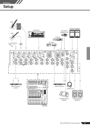
Reference Setup Reference Guitar Bass Microphone DI Synthesizer Powered Speakers Foot Switch (YAMAHA FC5) Recorder CD Player Effect Processor (exciter) Effect Processor Headphones MG124CX Powered Monitor Speaker Powered Monitor Speakers MG124CX/MG124C Owner's Manual 11
Reference Setup Reference Guitar Bass Microphone DI Synthesizer Powered Speakers Foot Switch (YAMAHA FC5) Recorder CD Player Effect Processor (exciter) Effect Processor Headphones MG124CX Powered Monitor Speaker Powered Monitor Speakers MG124CX/MG124C Owner's Manual 11
Owner's Manual
Page 12
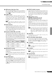
...-phased. The -34 to -16 scale is the LINE input adjustment range. 12 MG124CX/MG124C Owner's Manual NOTE Patching external devices via an INSERT jack requires a special insert cable such as ...ON F G H A A B B C C D D E ON F G H E ON F G H I I I /O jack Tip: OUT SSleleeevvee(G(Grorouunndd)) Ring: IN Tip: OUT Tip: IN To the output jack of the external processor To the INSERT I MG124CX 1 MIC Input Jacks (CHs 1 to 4, 5/6, 7/8) These are balanced XLR-type microphone input jacks (1:Ground; 2:Hot; 3:Cold). 2 LINE Input Jacks (CHs 1 to 4) These are balanced TRS...
...-phased. The -34 to -16 scale is the LINE input adjustment range. 12 MG124CX/MG124C Owner's Manual NOTE Patching external devices via an INSERT jack requires a special insert cable such as ...ON F G H A A B B C C D D E ON F G H E ON F G H I I I /O jack Tip: OUT SSleleeevvee(G(Grorouunndd)) Ring: IN Tip: OUT Tip: IN To the output jack of the external processor To the INSERT I MG124CX 1 MIC Input Jacks (CHs 1 to 4, 5/6, 7/8) These are balanced XLR-type microphone input jacks (1:Ground; 2:Hot; 3:Cold). 2 LINE Input Jacks (CHs 1 to 4) These are balanced TRS...
Owner's Manual
Page 13
... of compression applied to the Stereo buses engage the ON switch ( ). The BAL control knob sets the balance between the various channels. I jacks for monitoring. MG124CX/MG124C Owner's Manual 13 Setting the knob to the t position produces a flat response in ( ). On stereo channels, the signals from the channel to the AUX (AUX1...
... of compression applied to the Stereo buses engage the ON switch ( ). The BAL control knob sets the balance between the various channels. I jacks for monitoring. MG124CX/MG124C Owner's Manual 13 Setting the knob to the t position produces a flat response in ( ). On stereo channels, the signals from the channel to the AUX (AUX1...
Owner's Manual
Page 14
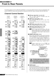
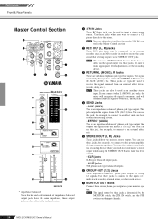
... the signal from AUX (AUX1) bus. NOTE The mixer's STEREO OUT Master Fader has no affect on the input channels. 14 MG124CX/MG124C Owner's Manual Reference Front & Rear Panels Master Control Section 2 1 5 3 7 4 6 8 B 9 0 C A D E G F H MG124CX * impedance balanced Since the hot and cold terminals of a multi-track recorder, external mixer, or other monitoring system. • EFFECT (AUX2...
... the signal from AUX (AUX1) bus. NOTE The mixer's STEREO OUT Master Fader has no affect on the input channels. 14 MG124CX/MG124C Owner's Manual Reference Front & Rear Panels Master Control Section 2 1 5 3 7 4 6 8 B 9 0 C A D E G F H MG124CX * impedance balanced Since the hot and cold terminals of a multi-track recorder, external mixer, or other monitoring system. • EFFECT (AUX2...
Owner's Manual
Page 15
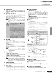
... channel PFL switch is sent to the C-R OUT jacks, PHONES jacks, and level meter. G ST Switch If this switch on when using the MG124CX, the Master EFFECT control does not affect the level of the signal sent from the 2TR IN jacks to the STEREO L/R buses. The PHONES jack... are sent to the STEREO L/R buses. • 2TR IN control Adjusts the level of loud noises that have XLR mic input jacks (CHs 1-4, 5/6, 7/8). MG124CX/MG124C Owner's Manual 15 Note, however, that you can adjust the levels of the signal selected by the MONITOR switch D, 2TR IN switch E and PFL switch. F GROUP 1-2...
... channel PFL switch is sent to the C-R OUT jacks, PHONES jacks, and level meter. G ST Switch If this switch on when using the MG124CX, the Master EFFECT control does not affect the level of the signal sent from the 2TR IN jacks to the STEREO L/R buses. The PHONES jack... are sent to the STEREO L/R buses. • 2TR IN control Adjusts the level of loud noises that have XLR mic input jacks (CHs 1-4, 5/6, 7/8). MG124CX/MG124C Owner's Manual 15 Note, however, that you can adjust the levels of the signal selected by the MONITOR switch D, 2TR IN switch E and PFL switch. F GROUP 1-2...
Owner's Manual
Page 16
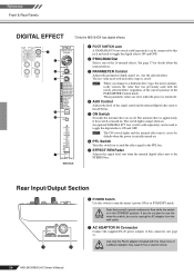
An optional YAMAHA FC5 foot switch (sold separately) can be connected to this jack and used to toggle the digital effects ON and OFF. 2 PROGRAM Dial Selects one ... the MG124CX has digital effects. 1 2 3 4 5 ON 6 7 MG124CX 1 FOOT SWITCH Jack A YAMAHA FC5 foot switch (sold separately) can be used to toggle the digital effects ON and OFF. Use of the signal sent from the internal digital effect unit to the AUX bus. 5 ON Switch Switches the internal effect on . CAUTION 16 MG124CX/MG124C Owner's Manual NOTE...
An optional YAMAHA FC5 foot switch (sold separately) can be connected to this jack and used to toggle the digital effects ON and OFF. 2 PROGRAM Dial Selects one ... the MG124CX has digital effects. 1 2 3 4 5 ON 6 7 MG124CX 1 FOOT SWITCH Jack A YAMAHA FC5 foot switch (sold separately) can be used to toggle the digital effects ON and OFF. Use of the signal sent from the internal digital effect unit to the AUX bus. 5 ON Switch Switches the internal effect on . CAUTION 16 MG124CX/MG124C Owner's Manual NOTE...
Owner's Manual
Page 17
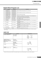
... plugs. The PARAMETER control adjusts the frequency of the LFO* that modulates the delay time. 14 PHASER LFO Frequency Phase modulation produces a cyclical phasing effect. MG124CX/MG124C Owner's Manual 17 Reference Front & Rear Panels Digital Effect Program List No Program Parameter Description 1 REVERB HALL 1 2 REVERB HALL 2 REVERB TIME REVERB TIME Reverb simulating a large...
... plugs. The PARAMETER control adjusts the frequency of the LFO* that modulates the delay time. 14 PHASER LFO Frequency Phase modulation produces a cyclical phasing effect. MG124CX/MG124C Owner's Manual 17 Reference Front & Rear Panels Digital Effect Program List No Program Parameter Description 1 REVERB HALL 1 2 REVERB HALL 2 REVERB TIME REVERB TIME Reverb simulating a large...
Owner's Manual
Page 18
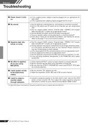
Then adjust the output signal by the MG124C feature in brackets: MG124CX (MG124C). 18 MG124CX/MG124C Owner's Manual Please connect to the AUX (AUX1) jack* and turn the PRE switch on each channel ON. Reference Troubleshooting ■ Power doesn't come on. ❑ Is ... switch set properly? ❑ Are your speaker cables connected properly, or are they shorted? ❑ If the above checks do not identify the problem, call Yamaha for service. (Refer to the page 71 for a list of service centers.) ■ Sound is faint, distorted, or noisy. ❑ Are the channel GAIN controls...
Then adjust the output signal by the MG124C feature in brackets: MG124CX (MG124C). 18 MG124CX/MG124C Owner's Manual Please connect to the AUX (AUX1) jack* and turn the PRE switch on each channel ON. Reference Troubleshooting ■ Power doesn't come on. ❑ Is ... switch set properly? ❑ Are your speaker cables connected properly, or are they shorted? ❑ If the above checks do not identify the problem, call Yamaha for service. (Refer to the page 71 for a list of service centers.) ■ Sound is faint, distorted, or noisy. ❑ Are the channel GAIN controls...
Owner's Manual
Page 19
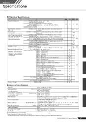
... AC 35 VCT, 0.94 A, Cable Length = 3.6 m 30 W Dimensions (W x H x D) 346.2 mm x 86.1 mm x 436.6 mm Net Weight 3.2 kg (MG124CX), 3 kg (MG124C) All faders are INPUT GAIN: maximum MIC to STEREO OUT 84 maximum when measured. Output impedance of shelving: 3 dB blow maximum variable level...Master fader and one CH GROUP OUT fader at minimum 0.1 % Hum & Noise Hum & Noise are measured with in brackets: MG124CX (MG124C) MG124CX/MG124C Owner's Manual 67 Internal Digital Effect* LED Level Meter 16 PROGRAM, PARAMETER control Foot Switch (Digital Effect On/Off) Pre MONITOR Level 2x12 points...
... AC 35 VCT, 0.94 A, Cable Length = 3.6 m 30 W Dimensions (W x H x D) 346.2 mm x 86.1 mm x 436.6 mm Net Weight 3.2 kg (MG124CX), 3 kg (MG124C) All faders are INPUT GAIN: maximum MIC to STEREO OUT 84 maximum when measured. Output impedance of shelving: 3 dB blow maximum variable level...Master fader and one CH GROUP OUT fader at minimum 0.1 % Hum & Noise Hum & Noise are measured with in brackets: MG124CX (MG124C) MG124CX/MG124C Owner's Manual 67 Internal Digital Effect* LED Level Meter 16 PROGRAM, PARAMETER control Foot Switch (Digital Effect On/Off) Pre MONITOR Level 2x12 points...
Owner's Manual
Page 20
...an output of +4 dB (1.23 V), or the nominal output level when the unit is described first, followed by the MG124C feature in brackets: MG124CX (MG124C) 68 MG124CX/MG124C Owner's Manual before clipping +24 dBu (12.3 V) +20 dBu (7.75 V) +20 dBu (7.75 V) +20 dBu (7.75 V) +10 dBV (3.16 V) +...(impedance balanced [Tip = HOT, Ring = COLD, Sleeve = GND]) Stereo phone jack Where 0 dBu = 0.775 Vrms and 0 dBV= 1 Vrms * The MG124CX feature is set to the maximum level. (All faders and level controls are at their maximum position.) ■ Output Specifications Output Connectors STEREO...
...an output of +4 dB (1.23 V), or the nominal output level when the unit is described first, followed by the MG124C feature in brackets: MG124CX (MG124C) 68 MG124CX/MG124C Owner's Manual before clipping +24 dBu (12.3 V) +20 dBu (7.75 V) +20 dBu (7.75 V) +20 dBu (7.75 V) +10 dBV (3.16 V) +...(impedance balanced [Tip = HOT, Ring = COLD, Sleeve = GND]) Stereo phone jack Where 0 dBu = 0.775 Vrms and 0 dBV= 1 Vrms * The MG124CX feature is set to the maximum level. (All faders and level controls are at their maximum position.) ■ Output Specifications Output Connectors STEREO...
Owner's Manual
Page 22
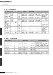
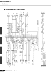
MG124CX/MG124C Owner's Manual 70 MIC [-60 to -16dBu] CH INPUT (CH1 to 4) LINE [-34 to +10dBu... YE EFFECT RETURN LO BA [-10dBu] [0dBu] RO DIGITAL EFFECT (DSP) BA AUX [-14dBu] PFL +15V IN only MG124CX +30dBu +20dBu +10dBu 0dBu -10dBu -20dBu -30dBu -40dBu -50dBu -60dBu CH IN LINE Gain:Min [+10dBu] CH...8dBu] L MONITOR OUT [+4dBu] R PHONES [3mW @ 40ohms] AUX SEND *1 [+4dBu] EFFECT SEND *1 [+4dBu] MONITOR MIX *1 MODEL FUNCTION NAME MG124CX AUX EFFECT MG124C AUX1 AUX2 Clip Level Clip Level Clip Level Clip Level AUX SEND *1 [+4dBu] GROUP OUT [+4dBu] AUX SEND *1 [Nominal:-6dB] GROUP...
MG124CX/MG124C Owner's Manual 70 MIC [-60 to -16dBu] CH INPUT (CH1 to 4) LINE [-34 to +10dBu... YE EFFECT RETURN LO BA [-10dBu] [0dBu] RO DIGITAL EFFECT (DSP) BA AUX [-14dBu] PFL +15V IN only MG124CX +30dBu +20dBu +10dBu 0dBu -10dBu -20dBu -30dBu -40dBu -50dBu -60dBu CH IN LINE Gain:Min [+10dBu] CH...8dBu] L MONITOR OUT [+4dBu] R PHONES [3mW @ 40ohms] AUX SEND *1 [+4dBu] EFFECT SEND *1 [+4dBu] MONITOR MIX *1 MODEL FUNCTION NAME MG124CX AUX EFFECT MG124C AUX1 AUX2 Clip Level Clip Level Clip Level Clip Level AUX SEND *1 [+4dBu] GROUP OUT [+4dBu] AUX SEND *1 [Nominal:-6dB] GROUP...

