
Owner's Manual
Page 5
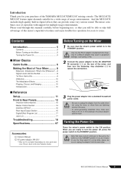
... Ambience 10 The Modulation Effects 10 Phasing, Chorus, and Flanging 10 Compression 10 ■ Reference Setup 11 Front & Rear Panels 12 Channel Control Section 12 Master Control Section 14 DIGITAL EFFECT 16 Rear Input/Output Section 16 Digital Effect Program List 17 Jack List 17 Troubleshooting 18 Specifications 67... there is 50 cm or more between the power adaptor and the mixer. If you will be able to take full advantage of the YAMAHA MG124CX/MG124C mixing console. Turning the Power On Press the mixer's power switch to use , so that trace current continues to flow...
... Ambience 10 The Modulation Effects 10 Phasing, Chorus, and Flanging 10 Compression 10 ■ Reference Setup 11 Front & Rear Panels 12 Channel Control Section 12 Master Control Section 14 DIGITAL EFFECT 16 Rear Input/Output Section 16 Digital Effect Program List 17 Jack List 17 Troubleshooting 18 Specifications 67... there is 50 cm or more between the power adaptor and the mixer. If you will be able to take full advantage of the YAMAHA MG124CX/MG124C mixing console. Turning the Power On Press the mixer's power switch to use , so that trace current continues to flow...
Owner's Manual
Page 12
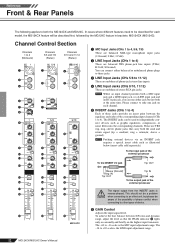
... the external processor CAUTION The signal output from the INSERT jacks is the LINE input adjustment range. 12 MG124CX/MG124C Owner's Manual Channel Control Section Channels 1 to 4 (Monaural) Channels 5/6 and 7/8 (Stereo) Channels 9/10 and 11/12 (Stereo) 1 1 4 2 3 3 5 6 6 7 7 8 9 9 0 0 0 A B C D E ON F G H A A B B C C D D E ON F G H E ON F G H I I I /O jack Tip: OUT SSleleeevvee(G(Grorouunndd)) Ring: IN Tip: OUT Tip: IN To the...
... the external processor CAUTION The signal output from the INSERT jacks is the LINE input adjustment range. 12 MG124CX/MG124C Owner's Manual Channel Control Section Channels 1 to 4 (Monaural) Channels 5/6 and 7/8 (Stereo) Channels 9/10 and 11/12 (Stereo) 1 1 4 2 3 3 5 6 6 7 7 8 9 9 0 0 0 A B C D E ON F G H A A B B C C D D E ON F G H E ON F G H I I I /O jack Tip: OUT SSleleeevvee(G(Grorouunndd)) Ring: IN Tip: OUT Tip: IN To the...
Owner's Manual
Page 13
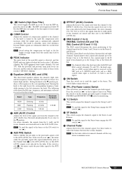
...-fader signal is output to the PHONES and MONITOR OUT I ) to the buses. On stereo channels (5/6, 7/8, 9/10, or 11/12), the signals from the L (odd) and R (even) channels are detected, and the indicator lights red if either of the channel...to the Stereo L bus; Press the switch in ( ). NOTE Set the fader sliders for monitoring. Channels 9/10 and 11/12 have two bands: high and low. C EFFECT (AUX2) Controls Adjusts the level of compression applied to turn the HPF on ...Fader Adjusts the level of these faders to the Group 2 bus or the Stereo R bus. MG124CX/MG124C Owner's Manual 13
...-fader signal is output to the PHONES and MONITOR OUT I ) to the buses. On stereo channels (5/6, 7/8, 9/10, or 11/12), the signals from the L (odd) and R (even) channels are detected, and the indicator lights red if either of the channel...to the Stereo L bus; Press the switch in ( ). NOTE Set the fader sliders for monitoring. Channels 9/10 and 11/12 have two bands: high and low. C EFFECT (AUX2) Controls Adjusts the level of compression applied to turn the HPF on ...Fader Adjusts the level of these faders to the Group 2 bus or the Stereo R bus. MG124CX/MG124C Owner's Manual 13
Owner's Manual
Page 17
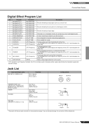
... Tip: Hot Sleeve: Ground Ring Sleeve Tip Sleeve Tip * These jacks will be unbalanced. An LFO is ideal for vocals. 11 CHORUS 1 12 CHORUS 2 13 FLANGER LFO Frequency LFO Frequency LFO Frequency Creates a thick sound by modulating the delay time. Jack List Input and Output Jacks MIC...control adjusts the frequency of the LFO* that modulates the delay time. 14 PHASER LFO Frequency Phase modulation produces a cyclical phasing effect. MG124CX/MG124C Owner's Manual 17 The PARAMETER control adjusts the frequency of the LFO* that modulates the delay time. 15 AUTO WAH LFO Frequency...
... Tip: Hot Sleeve: Ground Ring Sleeve Tip Sleeve Tip * These jacks will be unbalanced. An LFO is ideal for vocals. 11 CHORUS 1 12 CHORUS 2 13 FLANGER LFO Frequency LFO Frequency LFO Frequency Creates a thick sound by modulating the delay time. Jack List Input and Output Jacks MIC...control adjusts the frequency of the LFO* that modulates the delay time. 14 PHASER LFO Frequency Phase modulation produces a cyclical phasing effect. MG124CX/MG124C Owner's Manual 17 The PARAMETER control adjusts the frequency of the LFO* that modulates the delay time. 15 AUTO WAH LFO Frequency...
Owner's Manual
Page 19
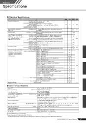
...+14 dBu @ 20 Hz-20 kHz, Input GAIN Control at minimum 0.1 % Hum & Noise Hum & Noise are measured with in brackets: MG124CX (MG124C) MG124CX/MG124C Owner's Manual 67 CH INPUT 1-4 MIC EIN (Equivalent Input Noise): Rs = 150 Ω, GAIN: maximum STEREO OUT STEREO OUT, GROUP...W Dimensions (W x H x D) 346.2 mm x 86.1 mm x 436.6 mm Net Weight 3.2 kg (MG124CX), 3 kg (MG124C) All faders are INPUT GAIN: maximum MIC to a 20 kHz filter with a 6 dB/octave filter @ 12.7 kHz; equivalent to STEREO OUT 84 maximum when measured. CHs 1-7/8 HIGH: 10 kHz (shelving) MID: 2.5 kHz...
...+14 dBu @ 20 Hz-20 kHz, Input GAIN Control at minimum 0.1 % Hum & Noise Hum & Noise are measured with in brackets: MG124CX (MG124C) MG124CX/MG124C Owner's Manual 67 CH INPUT 1-4 MIC EIN (Equivalent Input Noise): Rs = 150 Ω, GAIN: maximum STEREO OUT STEREO OUT, GROUP...W Dimensions (W x H x D) 346.2 mm x 86.1 mm x 436.6 mm Net Weight 3.2 kg (MG124CX), 3 kg (MG124C) All faders are INPUT GAIN: maximum MIC to a 20 kHz filter with a 6 dB/octave filter @ 12.7 kHz; equivalent to STEREO OUT 84 maximum when measured. CHs 1-7/8 HIGH: 10 kHz (shelving) MID: 2.5 kHz...
Owner's Manual
Page 20
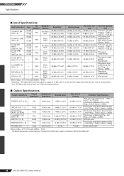
...(CHs 5/6, 7/8) -60 dB -16 dB 3kΩ 50-600Ω Mics -80 dBu (0.078 mV) -60 dBu (0.775 mV) -40 dBu (7.75 mV) -36 dBu (12.3 mV) -16 dBu (123 mV) -6 dBu (389 mV) XLR-3-31 type (balanced [1 = GND, 2 = HOT, 3 = COLD]) ST CH LINE INPUT (CHs 5/6, ... dB (1.23 V), or the nominal output level when the unit is described first, followed by the MG124C feature in brackets: MG124CX (MG124C) 68 MG124CX/MG124C Owner's Manual Reference Specifications ■ Input Specifications Input Connectors Gain Input Appropriate Impedance Impedance Sensitivity * Nominal Level Max. before...
...(CHs 5/6, 7/8) -60 dB -16 dB 3kΩ 50-600Ω Mics -80 dBu (0.078 mV) -60 dBu (0.775 mV) -40 dBu (7.75 mV) -36 dBu (12.3 mV) -16 dBu (123 mV) -6 dBu (389 mV) XLR-3-31 type (balanced [1 = GND, 2 = HOT, 3 = COLD]) ST CH LINE INPUT (CHs 5/6, ... dB (1.23 V), or the nominal output level when the unit is described first, followed by the MG124C feature in brackets: MG124CX (MG124C) 68 MG124CX/MG124C Owner's Manual Reference Specifications ■ Input Specifications Input Connectors Gain Input Appropriate Impedance Impedance Sensitivity * Nominal Level Max. before...
Owner's Manual
Page 22
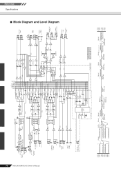
...[-10dBu] YE [0dBu] 3-Stage EQ ON [0dBu] YE CH Fader BA [-10dBu] LOW MID HIGH 3-Stage EQ BA [0dBu] L ST CH INPUT (CH9/10, 11/12) [-10dBu] R L/MONO RETURN [+4dBu] R L 2TR IN [-10dBV] [-7.8dBu] R HA [0dBu] ON 2-Stage EQ [0dBu] YE CH Fader BA [-10dBu] LOW...OUT [+4dBu] R L REC OUT [-10dBV] R [-7.8dBu] L MONITOR OUT [+4dBu] R PHONES [3mW @ 40ohms] AUX SEND *1 [+4dBu] EFFECT SEND *1 [+4dBu] MONITOR MIX *1 MODEL FUNCTION NAME MG124CX AUX EFFECT MG124C AUX1 AUX2 Clip Level Clip Level Clip Level Clip Level AUX SEND *1 [+4dBu] GROUP OUT [+4dBu] AUX SEND *1 [Nominal:-6dB] GROUP Fader...
...[-10dBu] YE [0dBu] 3-Stage EQ ON [0dBu] YE CH Fader BA [-10dBu] LOW MID HIGH 3-Stage EQ BA [0dBu] L ST CH INPUT (CH9/10, 11/12) [-10dBu] R L/MONO RETURN [+4dBu] R L 2TR IN [-10dBV] [-7.8dBu] R HA [0dBu] ON 2-Stage EQ [0dBu] YE CH Fader BA [-10dBu] LOW...OUT [+4dBu] R L REC OUT [-10dBV] R [-7.8dBu] L MONITOR OUT [+4dBu] R PHONES [3mW @ 40ohms] AUX SEND *1 [+4dBu] EFFECT SEND *1 [+4dBu] MONITOR MIX *1 MODEL FUNCTION NAME MG124CX AUX EFFECT MG124C AUX1 AUX2 Clip Level Clip Level Clip Level Clip Level AUX SEND *1 [+4dBu] GROUP OUT [+4dBu] AUX SEND *1 [Nominal:-6dB] GROUP Fader...