

Owner's Manual
Page 1
MIXING CONSOLE Owner's Manual Mode d'emploi Bedienungsanleitung M
MIXING CONSOLE Owner's Manual Mode d'emploi Bedienungsanleitung M
Owner's Manual
Page 2
...ann het einde van de levensduur afdankt of the following measures: Relocate either this manual, meets FCC requirements. NOTE: This product has been tested and found in is found to be determined by Yamaha Corporation of radio or TV interference, relocate/reorient the antenna. If the antenna ...lead-in the users manual, may void your retailer or Yamaha Service Center as small chemical waste. VAROITUS Paristo voi räjä...
...ann het einde van de levensduur afdankt of the following measures: Relocate either this manual, meets FCC requirements. NOTE: This product has been tested and found in is found to be determined by Yamaha Corporation of radio or TV interference, relocate/reorient the antenna. If the antenna ...lead-in the users manual, may void your retailer or Yamaha Service Center as small chemical waste. VAROITUS Paristo voi räjä...

Owner's Manual
Page 3
... so is a fire and electrical shock hazard. • Do not modify the unit. Never pull the cord. Keep This Manual For Future Reference. iii M2500-Owner's Manual Consult your dealer about replacing defective components. Use two or more people to carry it. • Hold the power cord plug when disconnecting..., be careful not to place heavy objects on the power supply unit. Using the unit in this unit or allow water to enter this Owner's Manual or as marked on a power cord covered by a carpet. • If you continue using the unit without heeding this instruction, fire...
... so is a fire and electrical shock hazard. • Do not modify the unit. Never pull the cord. Keep This Manual For Future Reference. iii M2500-Owner's Manual Consult your dealer about replacing defective components. Use two or more people to carry it. • Hold the power cord plug when disconnecting..., be careful not to place heavy objects on the power supply unit. Using the unit in this unit or allow water to enter this Owner's Manual or as marked on a power cord covered by a carpet. • If you continue using the unit without heeding this instruction, fire...

Owner's Manual
Page 4
...scene memory, PAN control that you for purchasing the Yamaha M2500 mixing console. In order to take full advantage of basic mixing console opera- This manual bases its explanation on the M2500-24. Note: • This manual assumes that is scene memory 30 Modes of the ...41 Other 42 Dimensions 43 MIDI data format 44 MIDI Implementation Chart 45 1 M2500-Owner's Manual Introduction Thank you have an understanding of the M2500's functionality and ensure trouble-free use, please read this manual carefully. Differences in the specifications of the system 2 Control panel ...
...scene memory, PAN control that you for purchasing the Yamaha M2500 mixing console. In order to take full advantage of basic mixing console opera- This manual bases its explanation on the M2500-24. Note: • This manual assumes that is scene memory 30 Modes of the ...41 Other 42 Dimensions 43 MIDI data format 44 MIDI Implementation Chart 45 1 M2500-Owner's Manual Introduction Thank you have an understanding of the M2500's functionality and ensure trouble-free use, please read this manual carefully. Differences in the specifications of the system 2 Control panel ...

Owner's Manual
Page 5
... output. This is ideal for each channel is also provided. • An INSERT I/O jack is convenient when using the M2500 as a stage monitor console. • The Scene Memory function allows you to be switched on/off individually for a wide range...are provided. Mute group switch settings allow scene memories 1-8 to individually add/remove eight sets of the system • The M2500-24 {32/40C/48C/56C} provides 24 {32/40/48/56} monaural input modules and four stereo input modules. ...well as one of the AUX 1-2, 2-6, 7-10, 11-14, STEREO, or MONO/C buses. 2 M2500-Owner's Manual
... output. This is ideal for each channel is also provided. • An INSERT I/O jack is convenient when using the M2500 as a stage monitor console. • The Scene Memory function allows you to be switched on/off individually for a wide range...are provided. Mute group switch settings allow scene memories 1-8 to individually add/remove eight sets of the system • The M2500-24 {32/40C/48C/56C} provides 24 {32/40/48/56} monaural input modules and four stereo input modules. ...well as one of the AUX 1-2, 2-6, 7-10, 11-14, STEREO, or MONO/C buses. 2 M2500-Owner's Manual

Owner's Manual
Page 6
... curve. E 80 (high pass filter) switch This switches the high pass filter on /off . Control panel Input channel section Monaural input channels The M2500-24 {32/40C/48C/56C} provides 24 {32/ 40/48/56} input channels. When the switch is pressed in ( ), the high pass filter is..., center frequency, and gain range of each input channel are the same for all models of +10 dB to switch between pre/post fader. 3 M2500-Owner's Manual When the switch is shown below 80 Hz will be attenuated by 26 dB. Nominal level (0 dB) is when the control is at which the...
... curve. E 80 (high pass filter) switch This switches the high pass filter on /off . Control panel Input channel section Monaural input channels The M2500-24 {32/40C/48C/56C} provides 24 {32/ 40/48/56} input channels. When the switch is pressed in ( ), the high pass filter is..., center frequency, and gain range of each input channel are the same for all models of +10 dB to switch between pre/post fader. 3 M2500-Owner's Manual When the switch is shown below 80 Hz will be attenuated by 26 dB. Nominal level (0 dB) is when the control is at which the...

Owner's Manual
Page 7
.... If ST is on , movements of the monaural input channel will affect the signal levels sent to GROUP buses 1-8 as follows, depending on Signal level 4 M2500-Owner's Manual ODD C PAN control EVEN Signal sent to GROUP buses 1/3/5/7 Signal sent to the STEREO bus (L/R) and MONO/C bus as a conventional channel assign switch. When...
.... If ST is on , movements of the monaural input channel will affect the signal levels sent to GROUP buses 1-8 as follows, depending on Signal level 4 M2500-Owner's Manual ODD C PAN control EVEN Signal sent to GROUP buses 1/3/5/7 Signal sent to the STEREO bus (L/R) and MONO/C bus as a conventional channel assign switch. When...

Owner's Manual
Page 8
... OUT and PHONES jacks. q In normal mode You can also use the PFL switch (O) to turn the monaural input channel on the mode of the M2500. M PEAK/NOM/SIGNAL indicators These three indicators allow you can use the ON/EDIT switch to monitor the signal from CPU J K GROUP AUX 1 3 5 7 1 3 5 7 9 ...PAN ST MONO LCR AUX1 AUX2 AUX3 AUX4 AUX5 9 8 PRE AUX6 AUX 7-10 Same as AUX 3-6 AUX 11-14 Same as AUX 3-6 PFL O 5 M2500-Owner's Manual Control panel L ON/EDIT switch / ON, CHECK indicators The function of this switch is on / off setting will light when the signal reaches a level 13...
... OUT and PHONES jacks. q In normal mode You can also use the PFL switch (O) to turn the monaural input channel on the mode of the M2500. M PEAK/NOM/SIGNAL indicators These three indicators allow you can use the ON/EDIT switch to monitor the signal from CPU J K GROUP AUX 1 3 5 7 1 3 5 7 9 ...PAN ST MONO LCR AUX1 AUX2 AUX3 AUX4 AUX5 9 8 PRE AUX6 AUX 7-10 Same as AUX 3-6 AUX 11-14 Same as AUX 3-6 PFL O 5 M2500-Owner's Manual Control panel L ON/EDIT switch / ON, CHECK indicators The function of this switch is on / off setting will light when the signal reaches a level 13...

Owner's Manual
Page 9
... input from the TRS phone connectors for stereo input channel 1. Band HIGH LOW Type Shelving Center frequency 10 kHz 100 Hz Gain ±15 dB 6 M2500-Owner's Manual Control panel Stereo input channels GAIN A +10 -30 B +10 -20 A B 1 2 3 HI -15 +15 LO 4 -15 +15 EQ 5 6 0 10...BAL L R ODD EVEN 8 1-2 ST 3-4 MONO 5-6 7-8 9 L CHECK ON ON/EDIT J 10 PEAK 5 NOM SIGNAL 0 5 10 20 30 40 50 60 PFL K M The M2500 provides four stereo input channels, allowing line-level stereo sources such as sub-mixers, effect processors, and CD players to -30 dB are slight differences...
... input from the TRS phone connectors for stereo input channel 1. Band HIGH LOW Type Shelving Center frequency 10 kHz 100 Hz Gain ±15 dB 6 M2500-Owner's Manual Control panel Stereo input channels GAIN A +10 -30 B +10 -20 A B 1 2 3 HI -15 +15 LO 4 -15 +15 EQ 5 6 0 10...BAL L R ODD EVEN 8 1-2 ST 3-4 MONO 5-6 7-8 9 L CHECK ON ON/EDIT J 10 PEAK 5 NOM SIGNAL 0 5 10 20 30 40 50 60 PFL K M The M2500 provides four stereo input channels, allowing line-level stereo sources such as sub-mixers, effect processors, and CD players to -30 dB are slight differences...

Owner's Manual
Page 10
...reaches nominal level (0 dB). • SIGNAL indicator This will be sent to monitor the signal from the MONITOR OUT and PHONES jacks. 7 M2500-Owner's Manual M PFL (pre-fader listen) switch When this switch and these switches are provided to the GROUP, STEREO. For details on check mode, ... STEREO bus. If these indicators will adjust the balance of the corresponding GROUP bus (1-2/3-4/56/7-8). H BAL control This adjusts the level balance of the M2500. When the channel is sent to the AUX buses 1-14. q In check mode When a scene is selected, the on/off status memorized in...
...reaches nominal level (0 dB). • SIGNAL indicator This will be sent to monitor the signal from the MONITOR OUT and PHONES jacks. 7 M2500-Owner's Manual M PFL (pre-fader listen) switch When this switch and these switches are provided to the GROUP, STEREO. For details on check mode, ... STEREO bus. If these indicators will adjust the balance of the corresponding GROUP bus (1-2/3-4/56/7-8). H BAL control This adjusts the level balance of the M2500. When the channel is sent to the AUX buses 1-14. q In check mode When a scene is selected, the on/off status memorized in...

Owner's Manual
Page 11
STEREO MONO/C MONO ST ON MONO ST MONO ST ON Control panel L INPUT A R ST CH 1 L INPUT B R L/MONO ST CH 2-4 INPUT R GAIN A 13 A B LO HI 45 2 stage EQ EQ 2 stage EQ K PEAK NOM SIGNAL L GAIN B 2 CHECK ON ON/EDIT J Control from CPU 8 BAL 9 GROUP AUX 1 3 5 7 1 3 5 7 9 11 13 L R 2 4 6 8 2 4 6 8 10 12 14 MONITOR INPUT MASTER (PFL) PFL AFL LR LR LR ST MONO AUX1 AUX2 AUX3 AUX4 AUX5 7 6 PRE AUX6 AUX 7-10 Same as AUX 3-6 AUX 11-14 Same as AUX 3-6 2 stage EQ EQ 2 stage EQ PFL M ST CH 2-4 Same as ST CH 1 GAIN LO HI 8 M2500-Owner's Manual
STEREO MONO/C MONO ST ON MONO ST MONO ST ON Control panel L INPUT A R ST CH 1 L INPUT B R L/MONO ST CH 2-4 INPUT R GAIN A 13 A B LO HI 45 2 stage EQ EQ 2 stage EQ K PEAK NOM SIGNAL L GAIN B 2 CHECK ON ON/EDIT J Control from CPU 8 BAL 9 GROUP AUX 1 3 5 7 1 3 5 7 9 11 13 L R 2 4 6 8 2 4 6 8 10 12 14 MONITOR INPUT MASTER (PFL) PFL AFL LR LR LR ST MONO AUX1 AUX2 AUX3 AUX4 AUX5 7 6 PRE AUX6 AUX 7-10 Same as AUX 3-6 AUX 11-14 Same as AUX 3-6 2 stage EQ EQ 2 stage EQ PFL M ST CH 2-4 Same as ST CH 1 GAIN LO HI 8 M2500-Owner's Manual

Owner's Manual
Page 12
... AUX5 10 ON 5 0 5 10 20 30 40 50 60 AFL AUX6 These are used to METER AUX OUT +4dB 1 AFL 3 AUX 2-6 Same as AUX 1 9 M2500-Owner's Manual C AFL (after -fader signal. Control panel A ON switches These turn AUX OUT 1-6 on , the MONITOR MASTER bus cannot be monitored from the MONITOR OUT/ PHONES...
... AUX5 10 ON 5 0 5 10 20 30 40 50 60 AFL AUX6 These are used to METER AUX OUT +4dB 1 AFL 3 AUX 2-6 Same as AUX 1 9 M2500-Owner's Manual C AFL (after -fader signal. Control panel A ON switches These turn AUX OUT 1-6 on , the MONITOR MASTER bus cannot be monitored from the MONITOR OUT/ PHONES...
Owner's Manual
Page 13
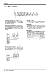
... the MONITOR OUT/PHONES jacks. PAN C L R ODD EVEN 1-2 ST 3-4 MONO 5-6 7-8 LCR 0 10 LEVEL ON AFL A7 / G1 0 10 LEVEL ON AFL A8 / G2 10 M2500-Owner's Manual Control panel A7/G1-A14/G8 section 1 2 0 10 LEVEL 0 10 LEVEL ON AFL A7 / G1 ON AFL A8 / G2 3 0 10 LEVEL ON AFL A9 / G3...
... the MONITOR OUT/PHONES jacks. PAN C L R ODD EVEN 1-2 ST 3-4 MONO 5-6 7-8 LCR 0 10 LEVEL ON AFL A7 / G1 0 10 LEVEL ON AFL A8 / G2 10 M2500-Owner's Manual Control panel A7/G1-A14/G8 section 1 2 0 10 LEVEL 0 10 LEVEL ON AFL A7 / G1 ON AFL A8 / G2 3 0 10 LEVEL ON AFL A9 / G3...

Owner's Manual
Page 14
.../EDIT ON/EDIT 10 5 0 5 10 20 30 40 50 60 AFL 10 5 0 5 10 20 30 40 50 60 AFL G1 / A7 G2 / A8 11 M2500-Owner's Manual Use the GROUP/AUX FLIP switch (page 14) to channels G1/A7-G8/A14 respectively, and will be output individually from the GRP/AUX OUT...
.../EDIT ON/EDIT 10 5 0 5 10 20 30 40 50 60 AFL 10 5 0 5 10 20 30 40 50 60 AFL G1 / A7 G2 / A8 11 M2500-Owner's Manual Use the GROUP/AUX FLIP switch (page 14) to channels G1/A7-G8/A14 respectively, and will be output individually from the GRP/AUX OUT...
Owner's Manual
Page 15
... MATRIX bus. The function of the PAN control will be sent directly to the MONO/C bus. (Refer to response curve diagram 2 on page 4.) 12 M2500-Owner's Manual q When the LCR switch is on PAN will adjust the pan of the signal that is sent from the GRP/AUX OUT G1/A7-G8...
... MATRIX bus. The function of the PAN control will be sent directly to the MONO/C bus. (Refer to response curve diagram 2 on page 4.) 12 M2500-Owner's Manual q When the LCR switch is on PAN will adjust the pan of the signal that is sent from the GRP/AUX OUT G1/A7-G8...
Owner's Manual
Page 16
.../AUX G2/A8-G8/A14 and AUX/GRP A8/G2-A14/G8 Same as G1/A7 and G7/A1 GROUP AUX GROUP/AUX FLIP 13 M2500-Owner's Manual If the input channel PFL switches are all off status memorized in that are switched off . Channels that scene will be indicated by the... lit/ dark status of the CHECK indicator. Control panel G Fader This adjusts the output level of the M2500. STEREO MONO/C G1/A7 G2/A8 G3/A9 G4...
.../AUX G2/A8-G8/A14 and AUX/GRP A8/G2-A14/G8 Same as G1/A7 and G7/A1 GROUP AUX GROUP/AUX FLIP 13 M2500-Owner's Manual If the input channel PFL switches are all off status memorized in that are switched off . Channels that scene will be indicated by the... lit/ dark status of the CHECK indicator. Control panel G Fader This adjusts the output level of the M2500. STEREO MONO/C G1/A7 G2/A8 G3/A9 G4...

Owner's Manual
Page 17
...mm faders to the AUX/GRP OUT jacks. GROUP When AUX is more convenient when you are using the M2500 as a "monitor console" to control individual monitor levels on stage, since you will be routed through the...G1 0 10 LEVEL ON AFL A8 / G2 A7/G1-A14/G8 section 14 M2500-Owner's Manual With this setting, AUX buses 7-14 can be used as group buses. Control panel GROUP/AUX FLIP switch The... M2500 provides a GROUP/ AUX FLIP switch that exchanges the output destinations of...
...mm faders to the AUX/GRP OUT jacks. GROUP When AUX is more convenient when you are using the M2500 as a "monitor console" to control individual monitor levels on stage, since you will be routed through the...G1 0 10 LEVEL ON AFL A8 / G2 A7/G1-A14/G8 section 14 M2500-Owner's Manual With this setting, AUX buses 7-14 can be used as group buses. Control panel GROUP/AUX FLIP switch The... M2500 provides a GROUP/ AUX FLIP switch that exchanges the output destinations of...

Owner's Manual
Page 18
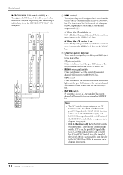
...; ON/EDIT ❍ Note: The output channels of GROUP buses 1-8 and AUX buses 7-14 will change in addition to the faders. Control panel 15 M2500-Owner's Manual When you change the setting of the GROUP/AUX FLIP switch, numerous functions of the output channels of AUX buses 1-6 are not affected by the...
...; ON/EDIT ❍ Note: The output channels of GROUP buses 1-8 and AUX buses 7-14 will change in addition to the faders. Control panel 15 M2500-Owner's Manual When you change the setting of the GROUP/AUX FLIP switch, numerous functions of the output channels of AUX buses 1-6 are not affected by the...
Owner's Manual
Page 19
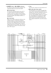
... CHECK indicator between lit/dark. (The current on/ off setting will allow you can be indicated by the lit/ dark status of MONO/C. 16 M2500-Owner's Manual F ON/EDIT switch / ON, CHECK indicators The function of this switch and these indicators will change depending on /off , turning this is switched...in that scene will be lit/dark to the matrix. C Fader This adjusts the ST OUT L/R output level. If the PFL switches of the M2500. D AFL switch Using this switch is switched on the mode of all input channels are switched off will be indicated by the lit/ dark ...
... CHECK indicator between lit/dark. (The current on/ off setting will allow you can be indicated by the lit/ dark status of MONO/C. 16 M2500-Owner's Manual F ON/EDIT switch / ON, CHECK indicators The function of this switch and these indicators will change depending on /off , turning this is switched...in that scene will be lit/dark to the matrix. C Fader This adjusts the ST OUT L/R output level. If the PFL switches of the M2500. D AFL switch Using this switch is switched on the mode of all input channels are switched off will be indicated by the lit/ dark ...

Owner's Manual
Page 20
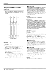
... can be output monaurally from CPU AFL 8 5 +4dB MONO/C MATRIX MASTER PFL INPUT MASTER Control panel L+R LEVEL ON PHONES L MONITOR OUT +4dB R MONO/C 17 M2500-Owner's Manual H AFL switch Using this AFL switch on (the indicator above the switch will light) will be monitored from the MONITOR OUT/PHONES jacks. Use the...
... can be output monaurally from CPU AFL 8 5 +4dB MONO/C MATRIX MASTER PFL INPUT MASTER Control panel L+R LEVEL ON PHONES L MONITOR OUT +4dB R MONO/C 17 M2500-Owner's Manual H AFL switch Using this AFL switch on (the indicator above the switch will light) will be monitored from the MONITOR OUT/PHONES jacks. Use the...

