
Owners Manual
Page 13
1 23 1 AE00101 65 4 793-146 CONTROL FUNCTION AE00102 DESCRIPTION 1 Carrying handles (shaded) 2 Fuel level gauge 3 Fuel tank cap 4 Oil filler cap 5 Recoil starter 6 Fuel cock 7 Muffler 1 32 1 7 793-147 AE00103 CONTROL PANEL 1 Engine switch 2 Twin Tech (parallel running terminal) 3 DC protector 4 Oil warning light 5 AC pilot light 6 Overload indicator light 7 AC receptacle 8 DC receptacle 9 Ground (Earth) terminal qw e r ty o i -8- u 793-148
1 23 1 AE00101 65 4 793-146 CONTROL FUNCTION AE00102 DESCRIPTION 1 Carrying handles (shaded) 2 Fuel level gauge 3 Fuel tank cap 4 Oil filler cap 5 Recoil starter 6 Fuel cock 7 Muffler 1 32 1 7 793-147 AE00103 CONTROL PANEL 1 Engine switch 2 Twin Tech (parallel running terminal) 3 DC protector 4 Oil warning light 5 AC pilot light 6 Overload indicator light 7 AC receptacle 8 DC receptacle 9 Ground (Earth) terminal qw e r ty o i -8- u 793-148
Owners Manual
Page 14
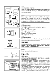
... then pull the recoil starter. NOTE: Press to the specified generator rated output if the DC protector turns off again, consult a Yamaha dealer. The parallel running requires two EF2400iS and the special cables. (The rated output in the Parallel Running Kit. Add oil and restart. 700-121 q w ...and the notes on . If it turns off . Consult a Yamaha dealer for parallel running is 3.6 kVA and the rated current is switched on usage are described in the PARALLEL RUNNING KIT OWNER'S MANUAL included in parallel running of two EF2400iS. cC Reduce the load to reset the DC protector. 1 I ...
... then pull the recoil starter. NOTE: Press to the specified generator rated output if the DC protector turns off again, consult a Yamaha dealer. The parallel running requires two EF2400iS and the special cables. (The rated output in the Parallel Running Kit. Add oil and restart. 700-121 q w ...and the notes on . If it turns off . Consult a Yamaha dealer for parallel running is 3.6 kVA and the rated current is switched on usage are described in the PARALLEL RUNNING KIT OWNER'S MANUAL included in parallel running of two EF2400iS. cC Reduce the load to reset the DC protector. 1 I ...
Owners Manual
Page 38
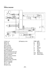
... R Br R O O t Br Br R R y Br R u Br G/Y R i GG @0 YY R R L L O O BW R O Y G L !8 !9 B/W B/W B/W O OO L L !6 !7 B/W Y B/W Y W B B/W O B/W !0 Y !1 B !2 L !5 B/W O Y OO G/Y G/Y !3 G/Y L B/W !4 Y Y o G/Y G/Y G/Y 770-054 1 Main coil 2 DC coil 3 Sub coil 4 DC rectifier 5 Control unit 6 AC pilot light 7 Parallel terminal 8 AC receptacle 9 Ground (Earth) terminal 0 Overload indicator light q DC receptacle w DC protector (breaker) e Engine switch r Oil warning light t Speed limiter assembly y Oil level gauge u T.C.I .
... R Br R O O t Br Br R R y Br R u Br G/Y R i GG @0 YY R R L L O O BW R O Y G L !8 !9 B/W B/W B/W O OO L L !6 !7 B/W Y B/W Y W B B/W O B/W !0 Y !1 B !2 L !5 B/W O Y OO G/Y G/Y !3 G/Y L B/W !4 Y Y o G/Y G/Y G/Y 770-054 1 Main coil 2 DC coil 3 Sub coil 4 DC rectifier 5 Control unit 6 AC pilot light 7 Parallel terminal 8 AC receptacle 9 Ground (Earth) terminal 0 Overload indicator light q DC receptacle w DC protector (breaker) e Engine switch r Oil warning light t Speed limiter assembly y Oil level gauge u T.C.I .
