Owners Manual
Page 5
... control switch 8 AC pilot light (Green 8 Overload indicator light (Red 9 Fuel tank cap 9 Fuel tank cap air vent knob 10 Fuel cock knob 10 Ground (Earth) terminal 10 Twin Tech 10 PREPARATION 11 Fuel 11 Engine oil 12 PRE-OPERATION CHECK 13 Pre-operation check 13 OPERATION 14 ...26 Muffler screen and spark arrester ......27 Fuel tank filter 29 STORAGE 30 Drain the fuel 30 Engine 32 TROUBLESHOOTING 33 Engine won't start 33 Generator won't produce power .........34 SPECIFICATIONS 36 Dimensions 36 Engine 36 Generator 36 CONSUMER INFORMATION 37 Identification number records ...
... control switch 8 AC pilot light (Green 8 Overload indicator light (Red 9 Fuel tank cap 9 Fuel tank cap air vent knob 10 Fuel cock knob 10 Ground (Earth) terminal 10 Twin Tech 10 PREPARATION 11 Fuel 11 Engine oil 12 PRE-OPERATION CHECK 13 Pre-operation check 13 OPERATION 14 ...26 Muffler screen and spark arrester ......27 Fuel tank filter 29 STORAGE 30 Drain the fuel 30 Engine 32 TROUBLESHOOTING 33 Engine won't start 33 Generator won't produce power .........34 SPECIFICATIONS 36 Dimensions 36 Engine 36 Generator 36 CONSUMER INFORMATION 37 Identification number records ...
Owners Manual
Page 11
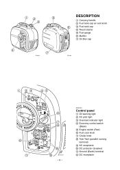
12 5 3 4 7 7DK-015 DESCRIPTION 1 Carrying handle 2 Fuel tank cap air vent knob 6 3 Fuel tank cap 4 Recoil starter 5 Fuel gauge 6 Muffler 7 Oil filler cap 7DK-016 1 23 45 w q 6 7 8 9 0 7DK-017 -6- AE00103 Control panel 1 Oil warning light 2 AC pilot light 3 Overload indicator light 4 Economy control switch (Black) 5 Engine switch (Red) 6 Fuel cock knob 7 Choke knob 8 Twin Tech (parallel running terminal) 9 AC receptacle 0 DC protector (breaker) q Ground (Earth) terminal w DC receptacle
12 5 3 4 7 7DK-015 DESCRIPTION 1 Carrying handle 2 Fuel tank cap air vent knob 6 3 Fuel tank cap 4 Recoil starter 5 Fuel gauge 6 Muffler 7 Oil filler cap 7DK-016 1 23 45 w q 6 7 8 9 0 7DK-017 -6- AE00103 Control panel 1 Oil warning light 2 AC pilot light 3 Overload indicator light 4 Economy control switch (Black) 5 Engine switch (Red) 6 Fuel cock knob 7 Choke knob 8 Twin Tech (parallel running terminal) 9 AC receptacle 0 DC protector (breaker) q Ground (Earth) terminal w DC receptacle
Owners Manual
Page 14
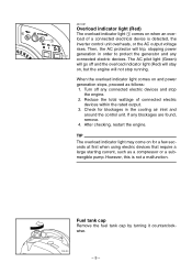
..., such as follows: 1. Then, the AC protector will trip, stopping power generation in the cooling air inlet and around the control unit. However, this is detected, the inverter control unit overheats, or the AC output voltage rises. Fuel tank cap Remove the fuel tank cap by turning it counterclockwise. 7DK-022 -9- 1 7DK-021 AE01087 Overload indicator...
..., such as follows: 1. Then, the AC protector will trip, stopping power generation in the cooling air inlet and around the control unit. However, this is detected, the inverter control unit overheats, or the AC output voltage rises. Fuel tank cap Remove the fuel tank cap by turning it counterclockwise. 7DK-022 -9- 1 7DK-021 AE01087 Overload indicator...
Owners Manual
Page 15
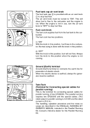
...generator must be earthed. 7DK-011 7DK-042a Twin Tech (Terminal for Connecting special cables for parallel running) This is the terminal for connecting special cables for prevention of two EF2000iS. The parallel running requires two EF2000iS... and the special cables. (The rated output in parallel running of electric shock. 1 2 1 2 7DK-023 1 7DK-024 Fuel tank cap air vent knob The fuel tank cap... "OFF" to the carburetor. Consult a Yamaha dealer for this position, fuel flows to stop fuel flow. Always turn the knob to this ...
...generator must be earthed. 7DK-011 7DK-042a Twin Tech (Terminal for Connecting special cables for parallel running) This is the terminal for connecting special cables for prevention of two EF2000iS. The parallel running requires two EF2000iS... and the special cables. (The rated output in parallel running of electric shock. 1 2 1 2 7DK-023 1 7DK-024 Fuel tank cap air vent knob The fuel tank cap... "OFF" to the carburetor. Consult a Yamaha dealer for this position, fuel flows to stop fuel flow. Always turn the knob to this ...

Owners Manual
Page 16
... a clean, dry, soft cloth, since fuel may overflow when the fuel warms up to the red level 2. Remove the fuel tank cap and fill the fuel into the tank up and expands. 9 After fill the fuel, make sure the fuel tank cap is highly flammable and poisonous. ly before... gasoline. The fuel level in the fuel tank can be checked through the fuel level gauge 1. 1 1 Fuel level gauge 7DK-037 2 Red line 3 Fuel level 3 7DK-028 Recommended fuel: Unleaded gasoline Fuel tank capacity: Total: 4.2 L (1.11 US gal, 0.92 Imp gal) 5 4 4 "F" 5 "E" Full Empty Your Yamaha engine has been...
... a clean, dry, soft cloth, since fuel may overflow when the fuel warms up to the red level 2. Remove the fuel tank cap and fill the fuel into the tank up and expands. 9 After fill the fuel, make sure the fuel tank cap is highly flammable and poisonous. ly before... gasoline. The fuel level in the fuel tank can be checked through the fuel level gauge 1. 1 1 Fuel level gauge 7DK-037 2 Red line 3 Fuel level 3 7DK-028 Recommended fuel: Unleaded gasoline Fuel tank capacity: Total: 4.2 L (1.11 US gal, 0.92 Imp gal) 5 4 4 "F" 5 "E" Full Empty Your Yamaha engine has been...
Owners Manual
Page 19
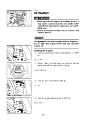
... a closed area or it will not move, turn the air vent knob to "ON" 1. 1 7 "ON" 1 7DK-039 - 14 - While holding the fuel tank cap so that it may cause unconsciousness and death within 7DK-047 a short time. Turn the engine switch (Red) to "ON" 1. 1 Air vent knob 7DK-035... 3. NOTICE The generator has been shipped without engine oil. Turn the economy control switch (Black) to "ON" 1. 1 "ON" 7DK-038 4. Do not start the engine till fill with the sufficient engine oil. Turn the fuel cock knob to "OFF" 1. 7DK-034 1 3 "OFF" 2. Starting...
... a closed area or it will not move, turn the air vent knob to "ON" 1. 1 7 "ON" 1 7DK-039 - 14 - While holding the fuel tank cap so that it may cause unconsciousness and death within 7DK-047 a short time. Turn the engine switch (Red) to "ON" 1. 1 Air vent knob 7DK-035... 3. NOTICE The generator has been shipped without engine oil. Turn the economy control switch (Black) to "ON" 1. 1 "ON" 7DK-038 4. Do not start the engine till fill with the sufficient engine oil. Turn the fuel cock knob to "OFF" 1. 7DK-034 1 3 "OFF" 2. Starting...

Owners Manual
Page 21
AE01025 Stopping the engine TIP 1 Turn off any electric devices. 7DK-047 3. Turn the fuel cock knob to "OFF" 1 after the engine has completely cooled down. 1 7DK-092 - 16 - Turn the fuel tank cap air vent knob to "OFF" 1. 1 1 "OFF" 7DK-045 5. Turn the economy control switch (Black) to "STOP" 1. 1 5 "STOP" 1 7DK-044 4. Turn the engine switch (Red) to "OFF" 1. 1 3 "OFF" 2. Disconnect any electric devices. 7DK-034 1.
AE01025 Stopping the engine TIP 1 Turn off any electric devices. 7DK-047 3. Turn the fuel cock knob to "OFF" 1 after the engine has completely cooled down. 1 7DK-092 - 16 - Turn the fuel tank cap air vent knob to "OFF" 1. 1 1 "OFF" 7DK-045 5. Turn the economy control switch (Black) to "STOP" 1. 1 5 "STOP" 1 7DK-044 4. Turn the engine switch (Red) to "OFF" 1. 1 3 "OFF" 2. Disconnect any electric devices. 7DK-034 1.
Owners Manual
Page 29
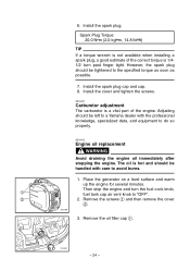
...torque wrench is not available when installing a spark plug, a good estimate of the engine. However, the spark plug should be left to a Yamaha dealer with care to the specified torque as soon as possible. 7. Adjusting should be handled with the professional knowledge, specialized data, and equipment to...part of the correct torque is 1/41/2 turn the fuel cock knob, 1 fuel tank cap air vent knob to do so properly. Install the spark plug. Install the spark plug cap and cap. 8. Install the cover and tighten the screws. Place the generator on a level surface and warm up the engine for...
...torque wrench is not available when installing a spark plug, a good estimate of the engine. However, the spark plug should be left to a Yamaha dealer with care to the specified torque as soon as possible. 7. Adjusting should be handled with the professional knowledge, specialized data, and equipment to...part of the correct torque is 1/41/2 turn the fuel cock knob, 1 fuel tank cap air vent knob to do so properly. Install the spark plug. Install the spark plug cap and cap. 8. Install the cover and tighten the screws. Place the generator on a level surface and warm up the engine for...

Owners Manual
Page 34
Clean the filter with gasoline. Wipe the filter and install it . 3. Remove the fuel tank cap and filter 1. 2. Install the fuel tank cap. WARNING Be sure the fuel tank cap is tightened securely. 7DK-069 - 29 - AE00471 Fuel tank filter 1 WARNING Never use the gasoline while smoking or in the vicinity of an open flame. 1. If damaged, replace it . 4.
Clean the filter with gasoline. Wipe the filter and install it . 3. Remove the fuel tank cap and filter 1. 2. Install the fuel tank cap. WARNING Be sure the fuel tank cap is tightened securely. 7DK-069 - 29 - AE00471 Fuel tank filter 1 WARNING Never use the gasoline while smoking or in the vicinity of an open flame. 1. If damaged, replace it . 4.

Owners Manual
Page 35
... devices. (unloaded operation) 9 Duration of the running engine depends on the 7DK-038 amount of the fuel left in approx. 20 mins. Turn the fuel tank cap air vent knob and fuel cock knob to "ON" 1. 1 7DK-039 1 4. time by run until it run - 1... ning out of your machine will require some preventive procedures to "STOP" 1. 2. Remove the fuel tank cap. Extract the fuel from the fuel tank into an approved gasoline container using 1 a commercially available handsiphon. The engine stops in the tank. - 30 - Check "SAFETY INFORMATION" ...
... devices. (unloaded operation) 9 Duration of the running engine depends on the 7DK-038 amount of the fuel left in approx. 20 mins. Turn the fuel tank cap air vent knob and fuel cock knob to "ON" 1. 1 7DK-039 1 4. time by run until it run - 1... ning out of your machine will require some preventive procedures to "STOP" 1. 2. Remove the fuel tank cap. Extract the fuel from the fuel tank into an approved gasoline container using 1 a commercially available handsiphon. The engine stops in the tank. - 30 - Check "SAFETY INFORMATION" ...

Owners Manual
Page 36
Tighten further if any screws, bolts and nuts are loose. 14. Turn the fuel cock knob to "OFF". 9. Remove the screws 1, and then remove the cover 2. 1 2 7DK-030 3 7DK-071 7. Drain the fuel from the carburetor by loosening the drain screw 3 on the carburetor float chamber. 8. Store the generator in a dry, well-ventilated place, with the cover placed over it. - 31 - Turn the engine switch to "OFF". 10. Turn the fuel tank cap air vent knob to "OFF". 13. Install the cover and tighten the screws. 12. Tighten the drain screw 3. 11. 6.
Tighten further if any screws, bolts and nuts are loose. 14. Turn the fuel cock knob to "OFF". 9. Remove the screws 1, and then remove the cover 2. 1 2 7DK-030 3 7DK-071 7. Drain the fuel from the carburetor by loosening the drain screw 3 on the carburetor float chamber. 8. Store the generator in a dry, well-ventilated place, with the cover placed over it. - 31 - Turn the engine switch to "OFF". 10. Turn the fuel tank cap air vent knob to "OFF". 13. Install the cover and tighten the screws. 12. Tighten the drain screw 3. 11. 6.

Owners Manual
Page 38
Supply fuel. 2 Fuel in tank .... Clean fuel line. 2 Clogged carburetor .... AE00512 TROUBLESHOOTING Engine won't start 1. Fuel tank cap air vent knob and fuel cock knob to combustion chamber. 7DK-091 2 No fuel in tank .... Engine oil system Insufficient 2 Oil level is low .... Add engine oil. 700-006 - 33 - Fuel systems No fuel supplied to "ON" 1. 2 Clogged fuel line .... Clean carburetor. 1 7DK-035 1 7DK-038 2.
Supply fuel. 2 Fuel in tank .... Clean fuel line. 2 Clogged carburetor .... AE00512 TROUBLESHOOTING Engine won't start 1. Fuel tank cap air vent knob and fuel cock knob to combustion chamber. 7DK-091 2 No fuel in tank .... Engine oil system Insufficient 2 Oil level is low .... Add engine oil. 700-006 - 33 - Fuel systems No fuel supplied to "ON" 1. 2 Clogged fuel line .... Clean carburetor. 1 7DK-035 1 7DK-038 2.


