Owners Manual
Page 5
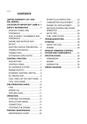
...NOTES 6 CONTROL FUNCTION 7 DESCRIPTION 7 CONTROL PANEL 7 OIL WARNING SYSTEM 8 ENGINE SWITCH 8 ECONOMY CONTROL SWITCH.........8 DC PROTECTOR 9 FUEL TANK CAP AIR VENT KNOB ....9 FUEL COCK KNOB 9 PRE-OPERATION CHECK 10 FUEL 10 ENGINE OIL 11 GROUND (Earth 11 OPERATION 12 STARTING THE ENGINE 12 APPLICATION... CHART 20 SPARK PLUG INSPECTION 22 CARBURETOR ADJUSTMENT.........22 ENGINE OIL REPLACEMENT ..........23 MUFFLER SCREEN AND SPARK ARRESTER 24 AIR FILTER 26 FUEL TANK FILTER 27 TROUBLESHOOTING 28 STORAGE 30 DRAIN THE FUEL 30 ENGINE 30 EXHAUST EMISSION CONTROL SYSTEM...
...NOTES 6 CONTROL FUNCTION 7 DESCRIPTION 7 CONTROL PANEL 7 OIL WARNING SYSTEM 8 ENGINE SWITCH 8 ECONOMY CONTROL SWITCH.........8 DC PROTECTOR 9 FUEL TANK CAP AIR VENT KNOB ....9 FUEL COCK KNOB 9 PRE-OPERATION CHECK 10 FUEL 10 ENGINE OIL 11 GROUND (Earth 11 OPERATION 12 STARTING THE ENGINE 12 APPLICATION... CHART 20 SPARK PLUG INSPECTION 22 CARBURETOR ADJUSTMENT.........22 ENGINE OIL REPLACEMENT ..........23 MUFFLER SCREEN AND SPARK ARRESTER 24 AIR FILTER 26 FUEL TANK FILTER 27 TROUBLESHOOTING 28 STORAGE 30 DRAIN THE FUEL 30 ENGINE 30 EXHAUST EMISSION CONTROL SYSTEM...
Owners Manual
Page 8
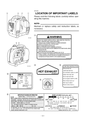
... knob ON 5 8Turn engine switch to ON 8Pull choke knob out 8Pull recoil starter 8Push choke knob in 7CG-25134-10 4 IMPORTANT ENGINE INFORMATION ENGINE AIR INDEX ( C a l i f o r n i a only) E M ENGINE FAMILY : zzzzzzzzzzzz REFER TO OWNER'S MANUAL FOR MAINTENANCE SPECIFICATIONS AND ADJUSTMENTS. 0 2 4 6 8 10 ...FUEL LEAKS. 8STOP ENGINE BEFORE REFUELING. 8DO NOT OPERATE NEAR FLAMMABLE MATERIALS. 8ELECTROCUTION CAN OCCUR IF GENERATOR IS USED IN RAIN, SNOW, OR NEAR WATER. YAMAHA MOTOR CO. FOR THE FOLLOWING USE: ENGINE OIL: SAE 10W-30 TYPE SE THIS ENGINE MEETS ...
... knob ON 5 8Turn engine switch to ON 8Pull choke knob out 8Pull recoil starter 8Push choke knob in 7CG-25134-10 4 IMPORTANT ENGINE INFORMATION ENGINE AIR INDEX ( C a l i f o r n i a only) E M ENGINE FAMILY : zzzzzzzzzzzz REFER TO OWNER'S MANUAL FOR MAINTENANCE SPECIFICATIONS AND ADJUSTMENTS. 0 2 4 6 8 10 ...FUEL LEAKS. 8STOP ENGINE BEFORE REFUELING. 8DO NOT OPERATE NEAR FLAMMABLE MATERIALS. 8ELECTROCUTION CAN OCCUR IF GENERATOR IS USED IN RAIN, SNOW, OR NEAR WATER. YAMAHA MOTOR CO. FOR THE FOLLOWING USE: ENGINE OIL: SAE 10W-30 TYPE SE THIS ENGINE MEETS ...

Owners Manual
Page 9
Also, be sure the fuel tank cap air vent knob is tightened when transporting the generator. 741-083 AE01019 ENGINE AND MUFFLER MAY BE HOT 9 Place the generator in a place where pedestrians or children are not likely to touch the generator. 741-084 9 Avoid placing any to spill any fuel on your ...engine in the vicinity of an open flame. 9 Take care not to get in your eye(s), see your clothes. 9 When operating or transporting the generator, be sure it is kept upright. Operate the engine in a well ventilated area. 741-081 741-082 AE01018 FUEL IS HIGHLY FLAMMABLE AND POISONOUS 9...
Also, be sure the fuel tank cap air vent knob is tightened when transporting the generator. 741-083 AE01019 ENGINE AND MUFFLER MAY BE HOT 9 Place the generator in a place where pedestrians or children are not likely to touch the generator. 741-084 9 Avoid placing any to spill any fuel on your ...engine in the vicinity of an open flame. 9 Take care not to get in your eye(s), see your clothes. 9 When operating or transporting the generator, be sure it is kept upright. Operate the engine in a well ventilated area. 741-081 741-082 AE01018 FUEL IS HIGHLY FLAMMABLE AND POISONOUS 9...
Owners Manual
Page 12
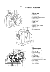
t !0 793-105a AE00103 CONTROL PANEL 1 Overload indicator light 2 AC pilot light 3 Oil warning light 4 Engine switch (Red) 5 Choke knob 6 Fuel cock knob 7 Ground (Earth) terminal 8 Economy control switch (Black) 9 DC protector 0 AC receptacle q DC receptacle qw e y !2 u AE00101 CONTROL FUNCTION r i o !1 !2 w e q 793-104a AE00102 DESCRIPTION 1 Fuel tank 2 Fuel tank cap 3 Fuel tank cap air vent knob 4 Fuel cock knob 5 Air filter cover 6 Spark plug 7 Muffler 8 Choke knob 9 Ground (Earth) terminal 0 Oil filler cap q Recoil starter w Carrying handle q w ert y !1 !0 o i u 793-106a -7-
t !0 793-105a AE00103 CONTROL PANEL 1 Overload indicator light 2 AC pilot light 3 Oil warning light 4 Engine switch (Red) 5 Choke knob 6 Fuel cock knob 7 Ground (Earth) terminal 8 Economy control switch (Black) 9 DC protector 0 AC receptacle q DC receptacle qw e y !2 u AE00101 CONTROL FUNCTION r i o !1 !2 w e q 793-104a AE00102 DESCRIPTION 1 Fuel tank 2 Fuel tank cap 3 Fuel tank cap air vent knob 4 Fuel cock knob 5 Air filter cover 6 Spark plug 7 Muffler 8 Choke knob 9 Ground (Earth) terminal 0 Oil filler cap q Recoil starter w Carrying handle q w ert y !1 !0 o i u 793-106a -7-

Owners Manual
Page 14
... knob must be found inside. When the engine is not in use, tighten the air vent knob clockwise until it turns off again, consult a Yamaha dealer. This will allow fuel to flow to the carburetor and the engine to stop fuel flow. cC Reduce the load to supply fuel. -9- w q 763-... q ON 707-098 Remove the cover 1 and the fuel cock lever can be used to the specified generator rated 763-224a output if the DC protector turns off automatically when the load exceeds the generator rated output. If for some reason the fuel cock knob cannot be turned, this lever can be...
... knob must be found inside. When the engine is not in use, tighten the air vent knob clockwise until it turns off again, consult a Yamaha dealer. This will allow fuel to flow to the carburetor and the engine to stop fuel flow. cC Reduce the load to supply fuel. -9- w q 763-... q ON 707-098 Remove the cover 1 and the fuel cock lever can be used to the specified generator rated 763-224a output if the DC protector turns off automatically when the load exceeds the generator rated output. If for some reason the fuel cock knob cannot be turned, this lever can be...

Owners Manual
Page 17
Turn the fuel cock knob to the "7" (ON) position. q 700-127 AE01109 OPERATION cC 9 The generator has been shipped without engine oil. Fill with oil or it will not start. 9 Do not tilt the generator when adding engine oil. q 1 7 "ON" 763-223 - 12 - While holding the fuel tank cap... so that it will not move, turn the air vent knob 1 turn counterclockwise to open the fuel tank air vent. 1 Air vent knob 707-097 2. Turn the engine switch...
Turn the fuel cock knob to the "7" (ON) position. q 700-127 AE01109 OPERATION cC 9 The generator has been shipped without engine oil. Fill with oil or it will not start. 9 Do not tilt the generator when adding engine oil. q 1 7 "ON" 763-223 - 12 - While holding the fuel tank cap... so that it will not move, turn the air vent knob 1 turn counterclockwise to open the fuel tank air vent. 1 Air vent knob 707-097 2. Turn the engine switch...

Owners Manual
Page 21
... will not stop the engine. 2. After checking, restart the engine. NOTE: 9 The generator AC output automatically resets when the engine is detected, the inverter control unit overheats, or the AC output voltage rises. q AE00953 Overload indicator light The ...overload indicator light 1 comes on when an overload of connected electric devices within the application range. 3. The AC pilot light (green) will then activate, 763-225 stopping power generation in the cooling air...
... will not stop the engine. 2. After checking, restart the engine. NOTE: 9 The generator AC output automatically resets when the engine is detected, the inverter control unit overheats, or the AC output voltage rises. q AE00953 Overload indicator light The ...overload indicator light 1 comes on when an overload of connected electric devices within the application range. 3. The AC pilot light (green) will then activate, 763-225 stopping power generation in the cooling air...

Owners Manual
Page 24
AE01025 STOPPING THE ENGINE NOTE: q 9 Turn off any electric devices. Turn the fuel tank cap air vent knob clockwise until it is finger-tight. 707-097a - 19 - Turn the engine switch (Red) to "OFF". 1 "OFF" q OFF 705-071d 4. q ON 761-078 2. Turn the fuel cock knob to the "5" (STOP) position. 1 5 "STOP" 763-223a 3. Disconnect any electric devices. 9 Turn the economy control switch (Black) to the 763-222 "3" (OFF) position. 1 3 "OFF" 1.
AE01025 STOPPING THE ENGINE NOTE: q 9 Turn off any electric devices. Turn the fuel tank cap air vent knob clockwise until it is finger-tight. 707-097a - 19 - Turn the engine switch (Red) to "OFF". 1 "OFF" q OFF 705-071d 4. q ON 761-078 2. Turn the fuel cock knob to the "5" (STOP) position. 1 5 "STOP" 763-223a 3. Disconnect any electric devices. 9 Turn the economy control switch (Black) to the 763-222 "3" (OFF) position. 1 3 "OFF" 1.

Owners Manual
Page 25
... damage. Check muffler screen and spark arrester. AE00401 PERIODIC MAINTENANCE AE00403 MAINTENANCE CHART Regular maintenance is recommended that these items be serviced by a Yamaha dealer. ** : Related to emission control system. - 20 - Replace if 0 necessary. * : It is most important for best performance...months months months or 50 Hr or 100 Hr or 300 Hr 0 Check and adjust 2.* *V*alve Clearance when engine is 0 cold. Air Filter Clean. Item 1. *S*park Plug Remarks Check condition. Replace if 0 necessary. Retighten or *replace gasket 0 4. *E*xhaust System if necessary...
... damage. Check muffler screen and spark arrester. AE00401 PERIODIC MAINTENANCE AE00403 MAINTENANCE CHART Regular maintenance is recommended that these items be serviced by a Yamaha dealer. ** : Related to emission control system. - 20 - Replace if 0 necessary. * : It is most important for best performance...months months months or 50 Hr or 100 Hr or 300 Hr 0 Check and adjust 2.* *V*alve Clearance when engine is 0 cold. Air Filter Clean. Item 1. *S*park Plug Remarks Check condition. Replace if 0 necessary. Retighten or *replace gasket 0 4. *E*xhaust System if necessary...

Owners Manual
Page 28
...and damage to "OFF". Add engine oil to drain the oil completely. 6. Turn the fuel tank cap air vent knob clockwise. 788-009 2. Tilt the generator to the upper level of the generator and remove the oil filler cap 4. 3 700-124 4. Attach the oil drain joint 5 to the oil...;C A YAMALUBE 4(10W-30) D SAE 10W C SAE #20 B SAE #30 32°F 80°F 700-065 5. AE01159 ENGINE OIL REPLACEMENT 1. Replace the generator on a level surface and warm q up the engine for several minutes. Remove the oil drain joint 3 pushing downward from the bottom of the filler hole...
...and damage to "OFF". Add engine oil to drain the oil completely. 6. Turn the fuel tank cap air vent knob clockwise. 788-009 2. Tilt the generator to the upper level of the generator and remove the oil filler cap 4. 3 700-124 4. Attach the oil drain joint 5 to the oil...;C A YAMALUBE 4(10W-30) D SAE 10W C SAE #20 B SAE #30 32°F 80°F 700-065 5. AE01159 ENGINE OIL REPLACEMENT 1. Replace the generator on a level surface and warm q up the engine for several minutes. Remove the oil drain joint 3 pushing downward from the bottom of the filler hole...

Owners Manual
Page 31
... not dripping. NOTE: Be sure the element sealing surface matches the air filter so there is no air leak. 710-059a - 26 - 9. Remove the cover 1. Wash the element in solvent and dry. Recommended oil: Foam-air-filter oil or SAE #20 motor oil cC Do not wring out... element. Oil the element and squeeze out excess oil. q 788-001 w e 2. Remove the air filter cover and element 4. 4. r 5. Remove the clip 2 holding the air filter cover 3. 788-002a 3. Insert the element into the air filter. Install the cover. 711-068a AE01029 AIR FILTER 1. This could cause it to tear. 6.
... not dripping. NOTE: Be sure the element sealing surface matches the air filter so there is no air leak. 710-059a - 26 - 9. Remove the cover 1. Wash the element in solvent and dry. Recommended oil: Foam-air-filter oil or SAE #20 motor oil cC Do not wring out... element. Oil the element and squeeze out excess oil. q 788-001 w e 2. Remove the air filter cover and element 4. 4. r 5. Remove the clip 2 holding the air filter cover 3. 788-002a 3. Insert the element into the air filter. Install the cover. 711-068a AE01029 AIR FILTER 1. This could cause it to tear. 6.

Owners Manual
Page 32
cC The engine should never run without the element; AE00471 FUEL TANK FILTER 1. If damaged, replace. 3. Wipe the filter and insert it. w Be sure the tank cap is tightened securely. 707-094 - 27 - Replace the air filter cover in the vicinity of an open flame. 7. Install the cover. q 1 Filter 2. Clean the filter with solvent. w Never use solvent while smoking or in its original position and install the clip. 8. excessive piston and cylinder wear may result. Remove the fuel tank cap and filter.
cC The engine should never run without the element; AE00471 FUEL TANK FILTER 1. If damaged, replace. 3. Wipe the filter and insert it. w Be sure the tank cap is tightened securely. 707-094 - 27 - Replace the air filter cover in the vicinity of an open flame. 7. Install the cover. q 1 Filter 2. Clean the filter with solvent. w Never use solvent while smoking or in its original position and install the clip. 8. excessive piston and cylinder wear may result. Remove the fuel tank cap and filter.
Owners Manual
Page 33
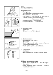
... .... Add engine oil. 700-006 763-223b 3. Remove carbon or wipe spark plug dry. 2 Faulty ignition system .... Consult dealer. 760-009 AE00785 Generator won 't start 1. Supply fuel. 2 Fuel in tank .... Compression Insufficient 2 Worn out piston and cylinder .... Stop the engine, then restart. 2 ...Safety device (DC protector) to combustion chamber. 2 No fuel in tank .... • Fuel tank cap air vent knob to "OPEN" (turn it 1 turn counterclockwise). • Fuel cock knob to "OFF" .... Fuel systems No fuel supplied to "OFF" ...
... .... Add engine oil. 700-006 763-223b 3. Remove carbon or wipe spark plug dry. 2 Faulty ignition system .... Consult dealer. 760-009 AE00785 Generator won 't start 1. Supply fuel. 2 Fuel in tank .... Compression Insufficient 2 Worn out piston and cylinder .... Stop the engine, then restart. 2 ...Safety device (DC protector) to combustion chamber. 2 No fuel in tank .... • Fuel tank cap air vent knob to "OPEN" (turn it 1 turn counterclockwise). • Fuel cock knob to "OFF" .... Fuel systems No fuel supplied to "OFF" ...
Owners Manual
Page 34
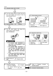
E Check engine oil level. I Engine does not start. N Check the following 9 Fuel line clogging O Clogged 9 Air cleaner element clogging. Consult a Yamaha dealer. C Does not flicker D Flickers. L Incorrect Replace or Adjust Gap. AE00515 A ENGINE DOES NOT START B Turn ...low Add engine oil. J Engine starts. H Pull the recoil starter and check the spark plug for spark strength. (See "WARNING") F OK Consult a Yamaha dealer. R Consult a Yamaha dealer. - 29 - K Check the spark plug. 9 Type: 9 Gap: w 9 To prevent FIRE HAZARDS be sure fuel is not present in the...
E Check engine oil level. I Engine does not start. N Check the following 9 Fuel line clogging O Clogged 9 Air cleaner element clogging. Consult a Yamaha dealer. C Does not flicker D Flickers. L Incorrect Replace or Adjust Gap. AE00515 A ENGINE DOES NOT START B Turn ...low Add engine oil. J Engine starts. H Pull the recoil starter and check the spark plug for spark strength. (See "WARNING") F OK Consult a Yamaha dealer. R Consult a Yamaha dealer. - 29 - K Check the spark plug. 9 Type: 9 Gap: w 9 To prevent FIRE HAZARDS be sure fuel is not present in the...

Owners Manual
Page 36
... EXHAUST EMISSION CONTROL SYSTEM AND COMPONENTS Item Acronym 9 CARB. MAGNETO ASSY EI (Electronic Ignition) PLUG, SPARK 9 CRANKCASE1 & HEAD PCV (Positive Crankcase CYLINDER1 Ventilation) 9 AIR FILTER ASSY ACL (Air Cleaner) 9 MUFF., 2, CAP, NET, WIRE2 & ARRESTER, SPARK The above items and the corresponding acronyms are provided in accordance with U.S. The acronyms conform to the...of the SAE's recommended practice document J1930, "Diagnostic Acronyms, Terms, and Definitions For Electrical/Electronic System". It is recommended that these items be serviced by a Yamaha dealer. - 31 -
... EXHAUST EMISSION CONTROL SYSTEM AND COMPONENTS Item Acronym 9 CARB. MAGNETO ASSY EI (Electronic Ignition) PLUG, SPARK 9 CRANKCASE1 & HEAD PCV (Positive Crankcase CYLINDER1 Ventilation) 9 AIR FILTER ASSY ACL (Air Cleaner) 9 MUFF., 2, CAP, NET, WIRE2 & ARRESTER, SPARK The above items and the corresponding acronyms are provided in accordance with U.S. The acronyms conform to the...of the SAE's recommended practice document J1930, "Diagnostic Acronyms, Terms, and Definitions For Electrical/Electronic System". It is recommended that these items be serviced by a Yamaha dealer. - 31 -
Owners Manual
Page 37
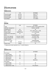
AE00707 GENERATOR Unit AC Output Rated Voltage V Rated frequency Hz Rated current A Rated Output VA Safty Device: Type DC Output Rated voltage V Rated current A Safety Device: Type ...) kW(HP)/r/min Hr L (Imp gal, US gal) L (Imp qt, US qt) Spark Plug: Type Spark Plug: Gap mm (in) Noise Level* dB (A) EF1000iS Forced air cooled 4-stroke gasoline OHV Vertical 1 cylinder 50 41.0 × 38.0 (1.61 × 1.50) 1.21 (1.67)/5,000 4.3 Unleaded gasoline 2.5 (0.55, 0.66) 0.32 (0.28, 0.34) TCI CR4HSB...
AE00707 GENERATOR Unit AC Output Rated Voltage V Rated frequency Hz Rated current A Rated Output VA Safty Device: Type DC Output Rated voltage V Rated current A Safety Device: Type ...) kW(HP)/r/min Hr L (Imp gal, US gal) L (Imp qt, US qt) Spark Plug: Type Spark Plug: Gap mm (in) Noise Level* dB (A) EF1000iS Forced air cooled 4-stroke gasoline OHV Vertical 1 cylinder 50 41.0 × 38.0 (1.61 × 1.50) 1.21 (1.67)/5,000 4.3 Unleaded gasoline 2.5 (0.55, 0.66) 0.32 (0.28, 0.34) TCI CR4HSB...


