
Owner's Manual
Page 3
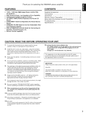
... for your dealer. 4. The openings on the rear panel if that the grounding or polarization of this Owner's Manual in a cool, dry, clean place - this YAMAHA stereo amplifier. When not planning to rain or water. 3. The apparatus is faulty. 9. Retain this unit must be set for future reference. 2. Therefore, avoid placing...
... for your dealer. 4. The openings on the rear panel if that the grounding or polarization of this Owner's Manual in a cool, dry, clean place - this YAMAHA stereo amplifier. When not planning to rain or water. 3. The apparatus is faulty. 9. Retain this unit must be set for future reference. 2. Therefore, avoid placing...
Owner's Manual
Page 4
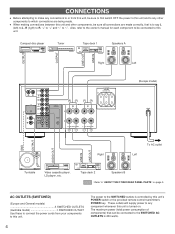
Also, refer to the owner's manual for each component to be connected to this unit. Compact disc player Tuner Tape deck 1 Speakers A OUTPUT OUTPUT LINE OUT LINE IN Right Left CD GND PHONO TUNER TAPE PB TAPE 1 REC OUT TAPE PB TAPE 2 REC OUT AUX MAIN IN COUPLER PRE OUT AC OUTLETB SWITCHED 200W MAX.TOTAL REMOTE CONTROL A SPEAKERS PHONO B A OR B:6ΩMIN./SPEAKER A B:l2ΩMIN./SPEAKER (Europe model) MAINS GND OUTPUT AUDIO OUT LINE IN LINE OUT Right To AC outlet Left Turntable Video cassette player, LD player, etc. AC OUTLETS (SWITCHED) (Europe and General models 3 ...
Also, refer to the owner's manual for each component to be connected to this unit. Compact disc player Tuner Tape deck 1 Speakers A OUTPUT OUTPUT LINE OUT LINE IN Right Left CD GND PHONO TUNER TAPE PB TAPE 1 REC OUT TAPE PB TAPE 2 REC OUT AUX MAIN IN COUPLER PRE OUT AC OUTLETB SWITCHED 200W MAX.TOTAL REMOTE CONTROL A SPEAKERS PHONO B A OR B:6ΩMIN./SPEAKER A B:l2ΩMIN./SPEAKER (Europe model) MAINS GND OUTPUT AUDIO OUT LINE IN LINE OUT Right To AC outlet Left Turntable Video cassette player, LD player, etc. AC OUTLETS (SWITCHED) (Europe and General models 3 ...
Owner's Manual
Page 5
... will not use ) Connecting the ground wire of this unit can be connected to this terminal will be output from the speakers. q If you have a YAMAHA turntable with a terminal for remote control, connect it to either the SPEAKERS A or B terminals. In that the PURE DIRECT switch on the front panel is...
... will not use ) Connecting the ground wire of this unit can be connected to this terminal will be output from the speakers. q If you have a YAMAHA turntable with a terminal for remote control, connect it to either the SPEAKERS A or B terminals. In that the PURE DIRECT switch on the front panel is...
Owner's Manual
Page 6
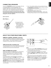
SPEAKERS * If you use two speaker systems, press both the A and B switches. 5 Play the source. 6 VOLUME l8 l6 l4 20 l2 24 l0 28 8 34 6 40 4 50 3 60 70 2 l 0 -dB Adjust to the desired output level. 7 If desired, adjust the BASS, TREBLE, BALANCE and LOUDNESS controls, etc. (Refer to page 8-9.) * If you select turntable as an input source (PHONO position), you should confirm that the PHONO (MM/MC) switch is reproduced purely and clearly by the turntable. (Refer to page 9.) To turn off the power Press the POWER switch again. 6 CD DIRECT AMPLIFIER Setting the INPUT ...
SPEAKERS * If you use two speaker systems, press both the A and B switches. 5 Play the source. 6 VOLUME l8 l6 l4 20 l2 24 l0 28 8 34 6 40 4 50 3 60 70 2 l 0 -dB Adjust to the desired output level. 7 If desired, adjust the BASS, TREBLE, BALANCE and LOUDNESS controls, etc. (Refer to page 8-9.) * If you select turntable as an input source (PHONO position), you should confirm that the PHONO (MM/MC) switch is reproduced purely and clearly by the turntable. (Refer to page 9.) To turn off the power Press the POWER switch again. 6 CD DIRECT AMPLIFIER Setting the INPUT ...
Owner's Manual
Page 7
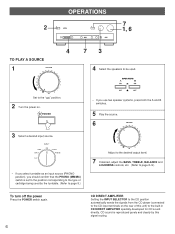
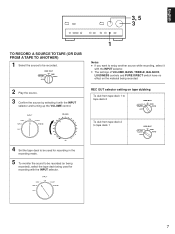
REC OUT 1 2 CD TUNER TAPE COPY 21 PHONO AUX 2 Play the source. 3 Confirm the source by selecting it with the INPUT selector and turning up the VOLUME control. q The settings of VOLUME, BASS, TREBLE, BALANCE, LOUDNESS controls and PURE DIRECT switch have no effect on tape dubbing To dub from tape deck 1 to tape deck 2 REC OUT 1 2 CD TUNER TAPE COPY 21 PHONO AUX To dub from tape deck 2 to be used for recording in the recording mode. 5 To monitor the sound to enjoy another source while recording, select it with the INPUT selector. REC OUT selector setting on the material ...
REC OUT 1 2 CD TUNER TAPE COPY 21 PHONO AUX 2 Play the source. 3 Confirm the source by selecting it with the INPUT selector and turning up the VOLUME control. q The settings of VOLUME, BASS, TREBLE, BALANCE, LOUDNESS controls and PURE DIRECT switch have no effect on tape dubbing To dub from tape deck 1 to tape deck 2 REC OUT 1 2 CD TUNER TAPE COPY 21 PHONO AUX To dub from tape deck 2 to be used for recording in the recording mode. 5 To monitor the sound to enjoy another source while recording, select it with the INPUT selector. REC OUT selector setting on the material ...
Owner's Manual
Page 8
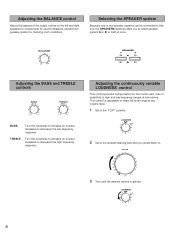
BALANCE l 0l 2 2 3 3 4 L5 4 5R SPEAKERS Adjusting the BASS and TREBLE controls BASS TREBLE BASS : Turn this clockwise to increase (or counterclockwise to decrease) the high frequency response. TREBLE : Turn this unit, the SPEAKERS switches allow you would listen to the "FLAT" position. LOUDNESS 30 dB 0 9 8 67 2 Set to the loudest listening level that you to select speaker system A or B, or both at once. VOLUME l8 l6 l4 20 l2 24 l0 28 8 34 6 40 4 50 3 60 70 2 l 0 -dB 3 Turn until the desired volume is adjustable to retain full tonal range at any ...
BALANCE l 0l 2 2 3 3 4 L5 4 5R SPEAKERS Adjusting the BASS and TREBLE controls BASS TREBLE BASS : Turn this clockwise to increase (or counterclockwise to decrease) the high frequency response. TREBLE : Turn this unit, the SPEAKERS switches allow you would listen to the "FLAT" position. LOUDNESS 30 dB 0 9 8 67 2 Set to the loudest listening level that you to select speaker system A or B, or both at once. VOLUME l8 l6 l4 20 l2 24 l0 28 8 34 6 40 4 50 3 60 70 2 l 0 -dB 3 Turn until the desired volume is adjustable to retain full tonal range at any ...
Owner's Manual
Page 9
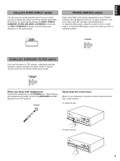
When listening with headphones Connect the headphones to the PHONES jack. PHONES Open/close the control door When it is not necessary to the OFF position. By doing so, the audio signals bypass the BASS, TREBLE, SUBSONIC FILTER, BALANCE, LOUDNESS controls and the PRE OUT/MAIN IN terminals, thus eliminating any alterations to "ON" position, undesirable ultra-lowfrequency signals caused by setting this switch so that it is released outward. PHONO (MM/MC) switch Select either MM or MC position depending on your audio sources by turntable rumble or warped records can enjoy the purest ...
When listening with headphones Connect the headphones to the PHONES jack. PHONES Open/close the control door When it is not necessary to the OFF position. By doing so, the audio signals bypass the BASS, TREBLE, SUBSONIC FILTER, BALANCE, LOUDNESS controls and the PRE OUT/MAIN IN terminals, thus eliminating any alterations to "ON" position, undesirable ultra-lowfrequency signals caused by setting this switch so that it is released outward. PHONO (MM/MC) switch Select either MM or MC position depending on your audio sources by turntable rumble or warped records can enjoy the purest ...
Owner's Manual
Page 10
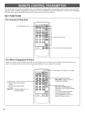
... a single cassette deck with your component's manual. KEY FUNCTIONS For Control of tape running. 10 On each component. Controls tape deck. * DIR A, B and DECK A/B are YAMAHA components designed for remote control compatibility, then this remote control transmitter will be the same.
... a single cassette deck with your component's manual. KEY FUNCTIONS For Control of tape running. 10 On each component. Controls tape deck. * DIR A, B and DECK A/B are YAMAHA components designed for remote control compatibility, then this remote control transmitter will be the same.
Owner's Manual
Page 11
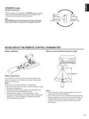
Notes q Use only AA, R6, UM-3 batteries for a long period of time. Within approximately 6 m (19.7 feet) 30° 30° Notes q There should be used for an extended period of this case, reposition the main unit to the main unit, the batteries are correct. (See the illustration inside the battery compartment.) q Remove the batteries if the remote control transmitter will not be no large obstacles between the remote control transmitter and the main unit. In this unit should be used closer to avoid direct lighting. 11 Clean the battery compartment thoroughly before...
Notes q Use only AA, R6, UM-3 batteries for a long period of time. Within approximately 6 m (19.7 feet) 30° 30° Notes q There should be used for an extended period of this case, reposition the main unit to the main unit, the batteries are correct. (See the illustration inside the battery compartment.) q Remove the batteries if the remote control transmitter will not be no large obstacles between the remote control transmitter and the main unit. In this unit should be used closer to avoid direct lighting. 11 Clean the battery compartment thoroughly before...
Owner's Manual
Page 12
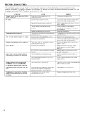
... simple measures suggested. The batteries of the BALANCE control. Speaker connections are connected in the SYMPTOM column, disconnect the power cord and contact your authorized YAMAHA dealer or service center for help. The PHONO (MM/MC) switch is pressed. The remote control transmitter does not work. Incorrect cord connections. Only one...
... simple measures suggested. The batteries of the BALANCE control. Speaker connections are connected in the SYMPTOM column, disconnect the power cord and contact your authorized YAMAHA dealer or service center for help. The PHONO (MM/MC) switch is pressed. The remote control transmitter does not work. Incorrect cord connections. Only one...
Owner's Manual
Page 13
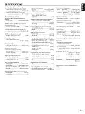
English SPECIFICATIONS Minimum RMS Output Power per Channel 8 ohms, 20 Hz to 20 kHz, 0.015% THD 110W+110W 6 ohms, 20 Hz to 20 kHz, 0.03% THD 130W+130W Dynamic Power per Channel (by IHF Dynamic Headroom measuring method) 8/6/4/2 ohms 150/200/250/330W DIN Standard Output Power per Channel [Europe model only] (4 ohms, 1 kHz, 0.7% THD 185W Dynamic Headroom [General model only] 8/6 ohms 1.35 dB/0.97 dB IEC Power [Europe model only] (8 ohms, 1 kHz, 0.01% THD 125W Power Band Width 8 ohms, 55W, 0.03% THD 10 Hz to 50 kHz Damping Factor 8 ohms, 20 Hz-20 kHz 320 or more Damping Factor (DIN) [...
English SPECIFICATIONS Minimum RMS Output Power per Channel 8 ohms, 20 Hz to 20 kHz, 0.015% THD 110W+110W 6 ohms, 20 Hz to 20 kHz, 0.03% THD 130W+130W Dynamic Power per Channel (by IHF Dynamic Headroom measuring method) 8/6/4/2 ohms 150/200/250/330W DIN Standard Output Power per Channel [Europe model only] (4 ohms, 1 kHz, 0.7% THD 185W Dynamic Headroom [General model only] 8/6 ohms 1.35 dB/0.97 dB IEC Power [Europe model only] (8 ohms, 1 kHz, 0.01% THD 125W Power Band Width 8 ohms, 55W, 0.03% THD 10 Hz to 50 kHz Damping Factor 8 ohms, 20 Hz-20 kHz 320 or more Damping Factor (DIN) [...