
Owner's Manual
Page 4
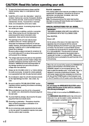
... a small amount of the unit. Using this unit with a higher voltage than specified is marked with the letter L or coloured RED. YAMAHA will rise rapidly; The wire which is coloured BROWN must be set in fire or other accidents. This state is on when the POWER ... "TROUBLESHOOTING" section regarding common operating errors before concluding that neither core is turned off and an appropriate 3 pin plug fitted. Install this manual carefully. When moving the unit, first disconnect the power plug and the wires connected to either end. Install the unit in the mains lead...
... a small amount of the unit. Using this unit with a higher voltage than specified is marked with the letter L or coloured RED. YAMAHA will rise rapidly; The wire which is coloured BROWN must be set in fire or other accidents. This state is on when the POWER ... "TROUBLESHOOTING" section regarding common operating errors before concluding that neither core is turned off and an appropriate 3 pin plug fitted. Install this manual carefully. When moving the unit, first disconnect the power plug and the wires connected to either end. Install the unit in the mains lead...
Owner's Manual
Page 6
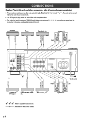
...TAPE OUT (REC) 4 IN (PLAY) 3 MD OUT (REC) 4 AUX L 3 * Right Left (Europe model) SPEAKERS R L A B CAUTION :SEE INSTRUCTION MANUAL FOR CORRECT SETTING. CONNECTIONS Caution: Plug in this unit and other components after all connections are completed. ● All connections must be correct, that is.... Also refer to "-". on the rear panel must be connected to page 5 for audio/video units except speakers. ● The output (or input) terminals of YAMAHA audio/video units numbered 1, 2, 3, 4, etc. TOTAL MAINS A OR B : 6ΩMIN. /SPEAKER A B : I2ΩMIN. /SPEAKER A OR...
...TAPE OUT (REC) 4 IN (PLAY) 3 MD OUT (REC) 4 AUX L 3 * Right Left (Europe model) SPEAKERS R L A B CAUTION :SEE INSTRUCTION MANUAL FOR CORRECT SETTING. CONNECTIONS Caution: Plug in this unit and other components after all connections are completed. ● All connections must be correct, that is.... Also refer to "-". on the rear panel must be connected to page 5 for audio/video units except speakers. ● The output (or input) terminals of YAMAHA audio/video units numbered 1, 2, 3, 4, etc. TOTAL MAINS A OR B : 6ΩMIN. /SPEAKER A B : I2ΩMIN. /SPEAKER A OR...
Owner's Manual
Page 10
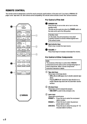
...keys These keys control compact disc players. * DISC SKIP is used functions of preset station numbers. Press these keys to control other YAMAHA components are the same as the corresponding keys on a single cassette tape deck with remote control compatibility, this key to control the ... station number. A/B/C/D/E: Press this remote control will reverse the tape direction on those components' instruction manuals for disc changers only. 3 Tuner keys These keys control tuners. If you have a YAMAHA CD player, tuner, tape deck, etc. REMOTE CONTROL The remote control is set in the ...
...keys These keys control compact disc players. * DISC SKIP is used functions of preset station numbers. Press these keys to control other YAMAHA components are the same as the corresponding keys on a single cassette tape deck with remote control compatibility, this key to control the ... station number. A/B/C/D/E: Press this remote control will reverse the tape direction on those components' instruction manuals for disc changers only. 3 Tuner keys These keys control tuners. If you have a YAMAHA CD player, tuner, tape deck, etc. REMOTE CONTROL The remote control is set in the ...


