
Owner's Manual
Page 2
... Channels 22 Selecting Fader Modes 22 Metering 23 Connections and Setup 25 Connections 25 Wordclock Connections and Settings .... 27 Input and Output Patching 29 Tutorial 31 Input and Output Patching 31 Setting the Input Levels 32 Pairing Channels 33 Setting the Routing 33 EQ'ing the Input Signals 35 Using... Digital Input Spec 62 Digital Output Spec 62 I/O SLOT Spec 63 MIDI/USB/WORD CLOCK I/O Spec .... 64 Dimensions 64 Options 65 Rack Mounting the 01V96i Using RK1 Rack Mount Kit 65 Index 66 01V96i Block Diagram.......End of Manual 01V96i Level Diagram .......End of Manual...
... Channels 22 Selecting Fader Modes 22 Metering 23 Connections and Setup 25 Connections 25 Wordclock Connections and Settings .... 27 Input and Output Patching 29 Tutorial 31 Input and Output Patching 31 Setting the Input Levels 32 Pairing Channels 33 Setting the Routing 33 EQ'ing the Input Signals 35 Using... Digital Input Spec 62 Digital Output Spec 62 I/O SLOT Spec 63 MIDI/USB/WORD CLOCK I/O Spec .... 64 Dimensions 64 Options 65 Rack Mounting the 01V96i Using RK1 Rack Mount Kit 65 Index 66 01V96i Block Diagram.......End of Manual 01V96i Level Diagram .......End of Manual...

Owner's Manual
Page 31
ton repeatedly until the Patch | Out Patch page appears. Tutorial 31 Tutorial This chapter describes operations on the 01V96i, organized according to modify the patching. 3. Press [ENTER] to Input Channels 25-32. 2. Press the DISPLAY ACCESS [PATCH] but- Press the [...24, and input signals from the instruments or mics connected to INPUT connectors 1-16 are sent to confirm the change . Tutorial 01V96i-Owner's Manual Input and Output Patching The 01V96i allows you want to confirm the change . In this case, select the desired input connector and channel number, and press...
ton repeatedly until the Patch | Out Patch page appears. Tutorial 31 Tutorial This chapter describes operations on the 01V96i, organized according to modify the patching. 3. Press [ENTER] to Input Channels 25-32. 2. Press the DISPLAY ACCESS [PATCH] but- Press the [...24, and input signals from the instruments or mics connected to INPUT connectors 1-16 are sent to confirm the change . Tutorial 01V96i-Owner's Manual Input and Output Patching The 01V96i allows you want to confirm the change . In this case, select the desired input connector and channel number, and press...

Owner's Manual
Page 32
...-fader input levels are the start point for control from instruments or mics connected to 0dB, then lower the corresponding [GAIN] controls. 01V96i-Owner's Manual They display channel input and output levels, and compressor and gate gain reduction amounts. Meter pages are metered. 6. When ...meters indicate the post-fader signal levels. To make sure that the LEVEL button (1) is on in the default state. 1. 32 Tutorial Setting the Input Levels The explanation here provides an example of adjusting the input level of the signals from the channel strip section. ...
...-fader input levels are the start point for control from instruments or mics connected to 0dB, then lower the corresponding [GAIN] controls. 01V96i-Owner's Manual They display channel input and output levels, and compressor and gate gain reduction amounts. Meter pages are metered. 6. When ...meters indicate the post-fader signal levels. To make sure that the LEVEL button (1) is on in the default state. 1. 32 Tutorial Setting the Input Levels The explanation here provides an example of adjusting the input level of the signals from the channel strip section. ...

Owner's Manual
Page 33
... of the signals for stereo operation. Note: If you want to operate the faders for the pair. Setting the Routing To record the 01V96i input signals to the second channel. INPUT connector 1 INPUT connector 2 INPUT connector 3 INPUT connector 4 INPUT connector 5 Input Patch Input ...Channels 1 Input Channels 2 Input Channels 3 Input Channels 4 Input Channels 4 ADAT OUT connector CH 1 CH 2 CH 3 CH 4 CH 5 Tutorial 01V96i-Owner's Manual Parameters are copied to an external device, you must specify the destination of the paired channels, and press the [SEL] button for the...
... of the signals for stereo operation. Note: If you want to operate the faders for the pair. Setting the Routing To record the 01V96i input signals to the second channel. INPUT connector 1 INPUT connector 2 INPUT connector 3 INPUT connector 4 INPUT connector 5 Input Patch Input ...Channels 1 Input Channels 2 Input Channels 3 Input Channels 4 Input Channels 4 ADAT OUT connector CH 1 CH 2 CH 3 CH 4 CH 5 Tutorial 01V96i-Owner's Manual Parameters are copied to an external device, you must specify the destination of the paired channels, and press the [SEL] button for the...

Owner's Manual
Page 34
...S button This button routes Input Channel signals to the Stereo Bus. 3 D button This button routes Input Channel signals to the Stereo Bus. 4. 34 Tutorial This section describes how to adjust the pan setting. 6. ING] button repeatedly to monitor the signals returned from the MONITOR OUT connectors and the PHONES.... 5. You can also use the 1-8 buttons to specify a Bus Out as the signal destination for each Input Channel is directly patched. 01V96i-Owner's Manual To do so, you to specify the output connectors or channels to which enables you will not be sent to the specified ...
...S button This button routes Input Channel signals to the Stereo Bus. 3 D button This button routes Input Channel signals to the Stereo Bus. 4. 34 Tutorial This section describes how to adjust the pan setting. 6. ING] button repeatedly to monitor the signals returned from the MONITOR OUT connectors and the PHONES.... 5. You can also use the 1-8 buttons to specify a Bus Out as the signal destination for each Input Channel is directly patched. 01V96i-Owner's Manual To do so, you to specify the output connectors or channels to which enables you will not be sent to the specified ...

Owner's Manual
Page 35
EQ'ing the Input Signals The 01V96i's Input Channels feature 4-band full parametric EQ. Press the DISPLAY ACCESS [PAN/ROUT- The Input Channels for which you want to route to apply EQ. 3. ... and HIGH band. This section describes how to use the EQ of the center frequency set via the F parameter control. ton to ADAT OUT channels 5-8. Tutorial 01V96i-Owner's Manual EQ'ing the Input Signals 35 7. In this example, Input Channel 9-12 signals are directly patched to change the values. Press the LAYER...
EQ'ing the Input Signals The 01V96i's Input Channels feature 4-band full parametric EQ. Press the DISPLAY ACCESS [PAN/ROUT- The Input Channels for which you want to route to apply EQ. 3. ... and HIGH band. This section describes how to use the EQ of the center frequency set via the F parameter control. ton to ADAT OUT channels 5-8. Tutorial 01V96i-Owner's Manual EQ'ing the Input Signals 35 7. In this example, Input Channel 9-12 signals are directly patched to change the values. Press the LAYER...

Owner's Manual
Page 36
..., the LOW band is now available for commonly-used instruments, allowing you want to "H. The LOW and HIGH GAIN controls function as desired. 01V96i-Owner's Manual SHELF" (low-shelving), and counter-clockwise all the way to set to "H. EQ library memory numbers 1-40 contain preset EQ settings...LOW-band EQ to apply EQ. 3. If these meters reach the "OVER" position, lower the pre-EQ signal level using the ATT. 36 Tutorial • F (Frequency) This parameter control specifies the center frequency for the other channels. Tip: The meters in the upper-left of the ...
..., the LOW band is now available for commonly-used instruments, allowing you want to "H. The LOW and HIGH GAIN controls function as desired. 01V96i-Owner's Manual SHELF" (low-shelving), and counter-clockwise all the way to set to "H. EQ library memory numbers 1-40 contain preset EQ settings...LOW-band EQ to apply EQ. 3. If these meters reach the "OVER" position, lower the pre-EQ signal level using the ATT. 36 Tutorial • F (Frequency) This parameter control specifies the center frequency for the other channels. Tip: The meters in the upper-left of the ...

Owner's Manual
Page 37
... four types of the page. To change the compressor type on the page, then rotate the Parameter wheel or press the [INC]/[DEC] buttons. Tutorial 01V96i-Owner's Manual sors: COMP (Compressor), EXPAND (Expander), COMP. (S) (Compander Soft), and COMP. (H) (Compander Hard). After you recall a gate program,...box. 5. To do so, move the cursor to access the Gate library. To use a compressor to adjust compressor parameters. The 01V96i displays the Dynamics | Comp Edit page, which enables you want to adjust gate parameters. This example uses one of the compressor. ...
... four types of the page. To change the compressor type on the page, then rotate the Parameter wheel or press the [INC]/[DEC] buttons. Tutorial 01V96i-Owner's Manual sors: COMP (Compressor), EXPAND (Expander), COMP. (S) (Compander Soft), and COMP. (H) (Compander Hard). After you recall a gate program,...box. 5. To do so, move the cursor to access the Gate library. To use a compressor to adjust compressor parameters. The 01V96i displays the Dynamics | Comp Edit page, which enables you want to adjust gate parameters. This example uses one of the compressor. ...

Owner's Manual
Page 38
...the RECALL button located to the left of Effects processors 1-4. press the [EFFECT] button repeatedly until the Patch | Effect page appears. 3. 38 Tutorial Using the Internal Effects The 01V96i features four internal multi-effects processors that can be used via Aux Send 1, and apply reverb to use internal Effects processor 1 via Aux... that the [ON] button for internal Effects processor 1 is different from the above . Press the LAYER [1-16] button. Select from the channel strip section. 01V96i-Owner's Manual ton repeatedly until the Effect | FX1 Lib page appears.
...the RECALL button located to the left of Effects processors 1-4. press the [EFFECT] button repeatedly until the Patch | Effect page appears. 3. 38 Tutorial Using the Internal Effects The 01V96i features four internal multi-effects processors that can be used via Aux Send 1, and apply reverb to use internal Effects processor 1 via Aux... that the [ON] button for internal Effects processor 1 is different from the above . Press the LAYER [1-16] button. Select from the channel strip section. 01V96i-Owner's Manual ton repeatedly until the Effect | FX1 Lib page appears.
Owner's Manual
Page 39
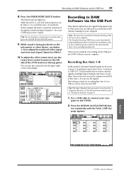
... Bus Outs 1-8 and sent to connect your DAW. You can be downloaded from Input Channels 1-16 to Aux 1 (Effects processor 1 input). The Yamaha Steinberg USB Driver can view the current level in the download file. Here's the procedure for recording Bus Outs 1/2 via USB to the installation guide...Software via the USB Port 39 8. For details on page 33. 1. For details on how to Bus Outs 1/2. Tutorial 01V96i-Owner's Manual While sound is being input to the 01V96i can use the rotary level control located on the left side of the ST IN section on your computer. ton ...
... Bus Outs 1-8 and sent to connect your DAW. You can be downloaded from Input Channels 1-16 to Aux 1 (Effects processor 1 input). The Yamaha Steinberg USB Driver can view the current level in the download file. Here's the procedure for recording Bus Outs 1/2 via USB to the installation guide...Software via the USB Port 39 8. For details on page 33. 1. For details on how to Bus Outs 1/2. Tutorial 01V96i-Owner's Manual While sound is being input to the 01V96i can use the rotary level control located on the left side of the ST IN section on your computer. ton ...
Owner's Manual
Page 40
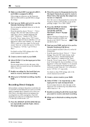
...to record, and start recording. 8. ton repeatedly until the Pan/Route | Rout1-16 page appears. As the ASIO driver, choose "Yamaha Steinberg USB ASIO" (Windows) / "Yamaha 01V96i" (Mac). • From the "Device" menu, choose "VST Connections." When you 're using Cubase AI, select the name ...If you 've finished recording, stop the DAW. 40 Tutorial 3. If you want to the owner's manual of the input ports you want to route to create a new stereo input. As the ASIO driver, choose "Yamaha Steinberg USB ASIO" (Windows) / "Yamaha 01V96i" (Mac). • From the "Device" menu, choose...
...to record, and start recording. 8. ton repeatedly until the Pan/Route | Rout1-16 page appears. As the ASIO driver, choose "Yamaha Steinberg USB ASIO" (Windows) / "Yamaha 01V96i" (Mac). • From the "Device" menu, choose "VST Connections." When you 're using Cubase AI, select the name ...If you 've finished recording, stop the DAW. 40 Tutorial 3. If you want to the owner's manual of the input ports you want to route to create a new stereo input. As the ASIO driver, choose "Yamaha Steinberg USB ASIO" (Windows) / "Yamaha 01V96i" (Mac). • From the "Device" menu, choose...

Owner's Manual
Page 41
...the channel strip section. 7. As the ASIO driver, choose "Yamaha Steinberg USB ASIO" (Windows) / "Yamaha 01V96i" (Mac). • From the "Device" menu, choose "VST Connections." In the Input tab, choose [Add Bus], set it to use the Yamaha Steinberg USB Driver. tively as necessary. Move the cursor to INPUT...monaural inputs. If you're using the included Cubase AI, set the device port to the 01V96i's Input Channels and monitored via the MONITOR OUT jacks or PHONES jack. Tutorial 01V96i-Owner's Manual Adjusting the Monitor Levels from the DAW 41 Adjusting the Monitor Levels from the ...
...the channel strip section. 7. As the ASIO driver, choose "Yamaha Steinberg USB ASIO" (Windows) / "Yamaha 01V96i" (Mac). • From the "Device" menu, choose "VST Connections." In the Input tab, choose [Add Bus], set it to use the Yamaha Steinberg USB Driver. tively as necessary. Move the cursor to INPUT...monaural inputs. If you're using the included Cubase AI, set the device port to the 01V96i's Input Channels and monitored via the MONITOR OUT jacks or PHONES jack. Tutorial 01V96i-Owner's Manual Adjusting the Monitor Levels from the DAW 41 Adjusting the Monitor Levels from the ...

Owner's Manual
Page 42
...'s Manual If you to of the 01V96i's mix parameters, internal effect processor settings, remote layers, and input/output patch settings. ORY Up [ ] or Down [ ] buttons to recall a Scene. 1. 42 Tutorial 9. Using Scene Memories Scene memories enable you select a Scene memory other than the currently-recalled Scene,... the [STEREO] fader. Now you can store 99 Scene memories, and recall any Scene by using the display pages or the controls on the 01V96i to the conditions you to name the Scene to select a Scene memory number. Scene memories #U ("Ud") and #0 ("00") are steadily lit...
...'s Manual If you to of the 01V96i's mix parameters, internal effect processor settings, remote layers, and input/output patch settings. ORY Up [ ] or Down [ ] buttons to recall a Scene. 1. 42 Tutorial 9. Using Scene Memories Scene memories enable you select a Scene memory other than the currently-recalled Scene,... the [STEREO] fader. Now you can store 99 Scene memories, and recall any Scene by using the display pages or the controls on the 01V96i to the conditions you to name the Scene to select a Scene memory number. Scene memories #U ("Ud") and #0 ("00") are steadily lit...

Owner's Manual
Page 43
... DISPLAY ACCESS [PATCH] but- You can reset all port names to their default names by moving the cursor to the OK button, then press [ENTER]. Tutorial 01V96i-Owner's Manual Edit the name, move the cursor to the INITIALIZE button, then pressing [ENTER]. ter box, then use the Parameter wheel or the [INC...
... DISPLAY ACCESS [PATCH] but- You can reset all port names to their default names by moving the cursor to the OK button, then press [ENTER]. Tutorial 01V96i-Owner's Manual Edit the name, move the cursor to the INITIALIZE button, then pressing [ENTER]. ter box, then use the Parameter wheel or the [INC...

Owner's Manual
Page 44
...Assignable layer. Use the LAYER [REMOTE] button to the YES button, then press [ENTER]. Set the TARGET parameter to control the assigned channels. 01V96i-Owner's Manual This custom layer is called "User Assignable layer." 1. A confirmation window appears. 3. You can store up to four 16-channel ...setups in the User CH Select window. Select the channels you wish to assign in four banks by combining any 01V96i channels (excluding the Stereo Out). 44 Tutorial Creating a Custom Layer by Combining Channels (User Assignable Layer) If you set the Remote Layer target to "USER ASSIGNABLE...
...Assignable layer. Use the LAYER [REMOTE] button to the YES button, then press [ENTER]. Set the TARGET parameter to control the assigned channels. 01V96i-Owner's Manual This custom layer is called "User Assignable layer." 1. A confirmation window appears. 3. You can store up to four 16-channel ...setups in the User CH Select window. Select the channels you wish to assign in four banks by combining any 01V96i channels (excluding the Stereo Out). 44 Tutorial Creating a Custom Layer by Combining Channels (User Assignable Layer) If you set the Remote Layer target to "USER ASSIGNABLE...

Owner's Manual
Page 45
... section, then rotate the Parameter wheel to set the level to raise the Oscillator level. Move the cursor to the parameter con- Tutorial 01V96i-Owner's Manual FORM parameter buttons, then press [ENTER]. When you can select the following parameters: 1 OSCILLATOR ON This parameter button ...output level. 4 ASSIGN section The buttons in this section select the Oscillator output. 2. Using the Oscillator 45 Using the Oscillator The 01V96i features an Oscillator you can damage the speakers. trol in the ASSIGN section. 6. Move the cursor to the parameter con- Oscillator ...
... section, then rotate the Parameter wheel to set the level to raise the Oscillator level. Move the cursor to the parameter con- Tutorial 01V96i-Owner's Manual FORM parameter buttons, then press [ENTER]. When you can select the following parameters: 1 OSCILLATOR ON This parameter button ...output level. 4 ASSIGN section The buttons in this section select the Oscillator output. 2. Using the Oscillator 45 Using the Oscillator The 01V96i features an Oscillator you can damage the speakers. trol in the ASSIGN section. 6. Move the cursor to the parameter con- Oscillator ...

Owner's Manual
Page 46
...desired BANK parameter button, then press [ENTER]. If you select a function that is executed based on the right and specify the number. 01V96i-Owner's Manual The corresponding bank is assigned to the USER DEFINED KEYS [1]-[8] buttons. To cancel the assignment, move the cursor to the User... Defined buttons in the 1-8 parameter boxes. 46 Tutorial Using the User Defined Keys You can use the assigned button as recalling a Scene or library memory), move the cursor to one of the...
...desired BANK parameter button, then press [ENTER]. If you select a function that is executed based on the right and specify the number. 01V96i-Owner's Manual The corresponding bank is assigned to the USER DEFINED KEYS [1]-[8] buttons. To cancel the assignment, move the cursor to the User... Defined buttons in the 1-8 parameter boxes. 46 Tutorial Using the User Defined Keys You can use the assigned button as recalling a Scene or library memory), move the cursor to one of the...

Owner's Manual
Page 47
...repeatedly to display the Utility | Lock page. 1 2 3 Tutorial This page contains the following website. To cancel all "safe" buttons simultaneously, move the cursor to the CLEAR ALL button, then press [ENTER]. 01V96i-Owner's Manual When you cannot cancel Operation Lock. The factory default...Lock is "1234." The Password window appears again. http://www.yamahaproaudio.com/ Using Operation Lock 47 Using Operation Lock The 01V96i features an Operation Lock function that you to select certain controls on the panel to exclude from the following parameters: 1 OPERATION...
...repeatedly to display the Utility | Lock page. 1 2 3 Tutorial This page contains the following website. To cancel all "safe" buttons simultaneously, move the cursor to the CLEAR ALL button, then press [ENTER]. 01V96i-Owner's Manual When you cannot cancel Operation Lock. The factory default...Lock is "1234." The Password window appears again. http://www.yamahaproaudio.com/ Using Operation Lock 47 Using Operation Lock The 01V96i features an Operation Lock function that you to select certain controls on the panel to exclude from the following parameters: 1 OPERATION...

Owner's Manual
Page 48
...Tutorial 3 PASSWORD This button enables you to change the password. Enter the current password in the PASSWORD field, and a new password in Step 2, move the cursor to first back up the data using the factory settings. 4. Follow the steps below the NEW PASSWORD field. After a moment, the 01V96i..."1234." Move the cursor to the OK button, then press [ENTER] to the INITIALIZE button, then press [ENTER]. To reset the 01V96i to the factory-preset values, all currently-recorded settings and restore the factory-preset values, and reset the Operation Lock password to its initial...
...Tutorial 3 PASSWORD This button enables you to change the password. Enter the current password in the PASSWORD field, and a new password in Step 2, move the cursor to first back up the data using the factory settings. 4. Follow the steps below the NEW PASSWORD field. After a moment, the 01V96i..."1234." Move the cursor to the OK button, then press [ENTER] to the INITIALIZE button, then press [ENTER]. To reset the 01V96i to the factory-preset values, all currently-recorded settings and restore the factory-preset values, and reset the Operation Lock password to its initial...
Reference Manual
Page 3
... Output Spec I/O SLOT Spec MIDI/USB/WORD CLOCK I/O Spec Dimensions Options Rack Mounting the 01V96i Using RK1 Rack Mount Kit Index 01V96i Block Diagram 01V96i Level Diagram 01V96i-Reference Manual PRECAUTIONS Welcome Package Contents About the included discs About the included DAW software About ... Selecting Layers Selecting Channels Selecting Fader Modes Metering Connections and Setup Connections Wordclock Connections and Settings Input and Output Patching Tutorial Input and Output Patching Setting the Input Levels Pairing Channels Setting the Routing EQ'ing the Input Signals Using the ...
... Output Spec I/O SLOT Spec MIDI/USB/WORD CLOCK I/O Spec Dimensions Options Rack Mounting the 01V96i Using RK1 Rack Mount Kit Index 01V96i Block Diagram 01V96i Level Diagram 01V96i-Reference Manual PRECAUTIONS Welcome Package Contents About the included discs About the included DAW software About ... Selecting Layers Selecting Channels Selecting Fader Modes Metering Connections and Setup Connections Wordclock Connections and Settings Input and Output Patching Tutorial Input and Output Patching Setting the Input Levels Pairing Channels Setting the Routing EQ'ing the Input Signals Using the ...