
Owner's Manual
Page 2
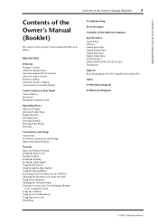
... Using the Oscillator 45 Using the User Defined Keys 46 Using Operation Lock 47 Initializing 48 Troubleshooting 49 Error messages 51 Contents of the Reference Manual 54 Specifications 55 General Spec 55 Libraries 60 Analog Input Spec 61 Analog Output Specs 61 Digital Input Spec 62 Digital Output Spec 62 ...I/O SLOT Spec 63 MIDI/USB/WORD CLOCK I/O Spec .... 64 Dimensions 64 Options 65 Rack Mounting the 01V96i Using RK1 Rack Mount Kit 65 Index 66 01V96i Block Diagram.......End of Manual 01V96i Level Diagram .......End of Manual 01V96i-Owner's Manual
... Using the Oscillator 45 Using the User Defined Keys 46 Using Operation Lock 47 Initializing 48 Troubleshooting 49 Error messages 51 Contents of the Reference Manual 54 Specifications 55 General Spec 55 Libraries 60 Analog Input Spec 61 Analog Output Specs 61 Digital Input Spec 62 Digital Output Spec 62 ...I/O SLOT Spec 63 MIDI/USB/WORD CLOCK I/O Spec .... 64 Dimensions 64 Options 65 Rack Mounting the 01V96i Using RK1 Rack Mount Kit 65 Index 66 01V96i Block Diagram.......End of Manual 01V96i Level Diagram .......End of Manual 01V96i-Owner's Manual
Owner's Manual
Page 7
... with your computer. Refer to the Steinberg website for choosing the Yamaha 01V96i Digital Mixing Console. It allows you to back up the settings of the included software and owner's manuals. • The included disc is driver software for connecting the 01V96i to save or recall..., and surround sound production. Do not use of the console, and to occur. ■ 01V96i Editor This is software that centrally manages multiple editors. 01V96i Editor also runs within this document) • Reference manual CD-ROM × 1 disc • DVD-ROM × 1 disc (included DAW software...
... with your computer. Refer to the Steinberg website for choosing the Yamaha 01V96i Digital Mixing Console. It allows you to back up the settings of the included software and owner's manuals. • The included disc is driver software for connecting the 01V96i to save or recall..., and surround sound production. Do not use of the console, and to occur. ■ 01V96i Editor This is software that centrally manages multiple editors. 01V96i Editor also runs within this document) • Reference manual CD-ROM × 1 disc • DVD-ROM × 1 disc (included DAW software...
Owner's Manual
Page 8
...that you take advantage of Adobe Reader can be able to view this Manual The 01V96i features two types of the functionality, the effect parameters, and MIDI-related functions. Using the PDF manual The reference manual is performed using the [DISPLAY] buttons or the Left Tab Scroll, ...com/ For details on the update procedure and settings, refer to simplify explanations, the procedures reference only the [DISPLAY] button method. You can press (e.g., ENTER and DISPLAY) and buttons that you must first install the "Yamaha Steinberg USB Driver" in square brackets, for terms and...
...that you take advantage of Adobe Reader can be able to view this Manual The 01V96i features two types of the functionality, the effect parameters, and MIDI-related functions. Using the PDF manual The reference manual is performed using the [DISPLAY] buttons or the Left Tab Scroll, ...com/ For details on the update procedure and settings, refer to simplify explanations, the procedures reference only the [DISPLAY] button method. You can press (e.g., ENTER and DISPLAY) and buttons that you must first install the "Yamaha Steinberg USB Driver" in square brackets, for terms and...

Owner's Manual
Page 37
...the Comp Edit page. Press the [ENTER] button to adjust gate parameters. Compressing the Input Signals 37 Compressing the Input Signals The 01V96i's Input Channels 1-32 feature individual channel compressors. nel to which enables you want to access the Gate library. sors: COMP (Compressor),... type on the page, then rotate the Parameter wheel or press the [INC]/[DEC] buttons. Tutorial 01V96i-Owner's Manual These processors feature different parameters. (See the Reference Manual for the parameters for control from the library. To use a compressor to the left corner of the...
...the Comp Edit page. Press the [ENTER] button to adjust gate parameters. Compressing the Input Signals 37 Compressing the Input Signals The 01V96i's Input Channels 1-32 feature individual channel compressors. nel to which enables you want to access the Gate library. sors: COMP (Compressor),... type on the page, then rotate the Parameter wheel or press the [INC]/[DEC] buttons. Tutorial 01V96i-Owner's Manual These processors feature different parameters. (See the Reference Manual for the parameters for control from the library. To use a compressor to the left corner of the...

Owner's Manual
Page 46
... to assign functions to the USER DEFINED KEYS [1]-[8] buttons. A function is usually executed on the right and specify the number. 01V96i-Owner's Manual Press the USER ACCESS [UTILITY] button to change the assignment quickly. When the window closes, the specified function is executed based ... 4 1-8 These parameter boxes enable you can assign any of more than 160 functions to USER DEFINED KEYS [1]-[8]. 4. See the Reference Manual for example, a function that appear in the center and right columns vary depending on specified numbers (for a complete list of the 1-8 param-
... to assign functions to the USER DEFINED KEYS [1]-[8] buttons. A function is usually executed on the right and specify the number. 01V96i-Owner's Manual Press the USER ACCESS [UTILITY] button to change the assignment quickly. When the window closes, the specified function is executed based ... 4 1-8 These parameter boxes enable you can assign any of more than 160 functions to USER DEFINED KEYS [1]-[8]. 4. See the Reference Manual for example, a function that appear in the center and right columns vary depending on specified numbers (for a complete list of the 1-8 param-

Owner's Manual
Page 54
54 Contents of the Reference Manual Contents of the Reference Manual How to Use This Reference Manual 1 Contents of the Owner's Manual (Booklet 3 Function Tree 4 Control Surface & Rear Panel 6 Control Surface 6 Rear Panel 10 Analog I/O & Digital I/O 12 Analog Inputs & Outputs 12 Digital Inputs &... 83 Nuendo/Cubase Remote Layer 93 Other DAW Remote Layer 94 MIDI Remote Layer 94 Machine Control Function 98 MIDI 100 MIDI & the 01V96i 100 MIDI Port Setup 101 Assigning Scenes to Program Changes for Remote Recall ...... 103 Assigning Parameters to Control Changes for Real-time Control...
54 Contents of the Reference Manual Contents of the Reference Manual How to Use This Reference Manual 1 Contents of the Owner's Manual (Booklet 3 Function Tree 4 Control Surface & Rear Panel 6 Control Surface 6 Rear Panel 10 Analog I/O & Digital I/O 12 Analog Inputs & Outputs 12 Digital Inputs &... 83 Nuendo/Cubase Remote Layer 93 Other DAW Remote Layer 94 MIDI Remote Layer 94 Machine Control Function 98 MIDI 100 MIDI & the 01V96i 100 MIDI Port Setup 101 Assigning Scenes to Program Changes for Remote Recall ...... 103 Assigning Parameters to Control Changes for Real-time Control...

Owner's Manual
Page 58
... filter @ 12.7 kHz; See "EQ Parameters" on page 60. 5. Hum & Noise are measured with infinite dB/octave attenuation. 3. See "Comp Parameters" on page 59. 01V96i-Owner's Manual Total harmonic distortion is measured with a 6 dB/octave filter @ 80 kHz. 2. See "Gate Parameters" on /off [email protected], 48kHz [email protected], 96kHz On/off - 100... V, 60 Hz 90 W 220-240 V, 50/60 Hz 90 W 148 x 548 x 436 mm 14 kg 0-35°C -20 to 60°C AC Cable CD-ROM (Reference Manual) DVD-ROM (DAW Software) Owner's Manual Digital interface card (MY16, MY8, MY4 series) RACK MOUNT KIT: RK1 1.
... filter @ 12.7 kHz; See "EQ Parameters" on page 60. 5. Hum & Noise are measured with infinite dB/octave attenuation. 3. See "Comp Parameters" on page 59. 01V96i-Owner's Manual Total harmonic distortion is measured with a 6 dB/octave filter @ 80 kHz. 2. See "Gate Parameters" on /off [email protected], 48kHz [email protected], 96kHz On/off - 100... V, 60 Hz 90 W 220-240 V, 50/60 Hz 90 W 148 x 548 x 436 mm 14 kg 0-35°C -20 to 60°C AC Cable CD-ROM (Reference Manual) DVD-ROM (DAW Software) Owner's Manual Digital interface card (MY16, MY8, MY4 series) RACK MOUNT KIT: RK1 1.
Reference Manual
Page 1
... 4 and following URL. Note: • If the Previous View / Next View buttons are not shown in your computer keyboard to a different page. Reference Manual How to Use This Reference Manual The 01V96i Reference Manual (this document) allows you to view this to quickly find the explanatory page you want. Searching for terms To search for a term, use...
... 4 and following URL. Note: • If the Previous View / Next View buttons are not shown in your computer keyboard to a different page. Reference Manual How to Use This Reference Manual The 01V96i Reference Manual (this document) allows you to view this to quickly find the explanatory page you want. Searching for terms To search for a term, use...

Reference Manual
Page 2
2 Contents Contents How to Use This Reference Manual 1 Contents of the Owner's Manual (Booklet 3 Function Tree 4 Control Surface & Rear Panel 6 Control Surface 6 Rear Panel 10 Analog I/O & Digital I/O 12 Analog...Remote Layer 93 Other DAW Remote Layer 94 MIDI Remote Layer 94 Machine Control Function 98 MIDI 100 MIDI & the 01V96i 100 MIDI Port Setup 101 Assigning Scenes to Program Changes for Remote Recall ...... 103 Assigning Parameters to Control Changes for... to Control Change Table 157 MIDI Data Format 173 MIDI Implementation Chart End of Manual 01V96i-Reference Manual
2 Contents Contents How to Use This Reference Manual 1 Contents of the Owner's Manual (Booklet 3 Function Tree 4 Control Surface & Rear Panel 6 Control Surface 6 Rear Panel 10 Analog I/O & Digital I/O 12 Analog...Remote Layer 93 Other DAW Remote Layer 94 MIDI Remote Layer 94 Machine Control Function 98 MIDI 100 MIDI & the 01V96i 100 MIDI Port Setup 101 Assigning Scenes to Program Changes for Remote Recall ...... 103 Assigning Parameters to Control Changes for... to Control Change Table 157 MIDI Data Format 173 MIDI Implementation Chart End of Manual 01V96i-Reference Manual
Reference Manual
Page 3
... Output Specs Digital Input Spec Digital Output Spec I/O SLOT Spec MIDI/USB/WORD CLOCK I/O Spec Dimensions Options Rack Mounting the 01V96i Using RK1 Rack Mount Kit Index 01V96i Block Diagram 01V96i Level Diagram 01V96i-Reference Manual PRECAUTIONS Welcome Package Contents About the included discs About the included DAW software About the utility software Firmware updates About...
... Output Specs Digital Input Spec Digital Output Spec I/O SLOT Spec MIDI/USB/WORD CLOCK I/O Spec Dimensions Options Rack Mounting the 01V96i Using RK1 Rack Mount Kit Index 01V96i Block Diagram 01V96i Level Diagram 01V96i-Reference Manual PRECAUTIONS Welcome Package Contents About the included discs About the included DAW software About the utility software Firmware updates About...

Reference Manual
Page 4
4 Function Tree Function Tree DISPLAY ACCESS Page numbers in parentheses ( ) are the page numbers of the Owner's Manual (booklet). BUTTON FUNCTION PAGE NAME LINK SCENE SCENE MEMORY 68 IN FADE INPUT FADE TIME 71 OUT FADE OUTPUT FADE TIME 71 RCL SAFE RECALL ... PARAMETER VIEW 31 37 24 FADER VIEW 32 38 CHANNEL LIBRARY 75 INPUT CH1-16 AUX VIEW 40 INPUT CH17-ST IN AUX VIEW 40 01V96i-Reference Manual
4 Function Tree Function Tree DISPLAY ACCESS Page numbers in parentheses ( ) are the page numbers of the Owner's Manual (booklet). BUTTON FUNCTION PAGE NAME LINK SCENE SCENE MEMORY 68 IN FADE INPUT FADE TIME 71 OUT FADE OUTPUT FADE TIME 71 RCL SAFE RECALL ... PARAMETER VIEW 31 37 24 FADER VIEW 32 38 CHANNEL LIBRARY 75 INPUT CH1-16 AUX VIEW 40 INPUT CH17-ST IN AUX VIEW 40 01V96i-Reference Manual

Reference Manual
Page 5
Function Tree FADER MODE BUTTON AUX1- AUX8 HOME (METER) FUNCTION SEND PAN VIEW1-16 VIEW17-STI CH1-32 ST IN MASTER EFFECT STEREO POSITION PAGE NAME LINK AUX1-AUX8 SEND 38 AUX1-AUX8 PAN 41 INPUT CH1-16 AUX VIEW 40 INPUT CH17-ST IN AUX VIEW 40 CH1-32 METER 8 ST IN METER 8 MASTER METER 8 EFFECT1-4 INPUT/OUTPUT METER 8 STEREO METER 8 METER POSITION 8 LAYER BUTTON 1-16 17-32 MASTER REMOTE FUNCTION USER DEFINED ProTools Nuendo Cubase General DAW USER ASSIGNABLE LAYER PAGE NAME LINK 8 8 8 94 83 93 93 94 110 Function Tree 5 01V96i-Reference Manual
Function Tree FADER MODE BUTTON AUX1- AUX8 HOME (METER) FUNCTION SEND PAN VIEW1-16 VIEW17-STI CH1-32 ST IN MASTER EFFECT STEREO POSITION PAGE NAME LINK AUX1-AUX8 SEND 38 AUX1-AUX8 PAN 41 INPUT CH1-16 AUX VIEW 40 INPUT CH17-ST IN AUX VIEW 40 CH1-32 METER 8 ST IN METER 8 MASTER METER 8 EFFECT1-4 INPUT/OUTPUT METER 8 STEREO METER 8 METER POSITION 8 LAYER BUTTON 1-16 17-32 MASTER REMOTE FUNCTION USER DEFINED ProTools Nuendo Cubase General DAW USER ASSIGNABLE LAYER PAGE NAME LINK 8 8 8 94 83 93 93 94 110 Function Tree 5 01V96i-Reference Manual

Reference Manual
Page 6
... Section (p. 9) SELECTED CHANNEL Section (p. 9) ST IN Section (p. 8) Channel Strip Section (p. 7) STEREO Section (p. 8) USER DEFINED KEYS Section (p. 9) Note: For details on the function of each item, refer to "Control Surface & Rear Panel" in the Owner's Manual. 01V96i-Reference Manual
... Section (p. 9) SELECTED CHANNEL Section (p. 9) ST IN Section (p. 8) Channel Strip Section (p. 7) STEREO Section (p. 8) USER DEFINED KEYS Section (p. 9) Note: For details on the function of each item, refer to "Control Surface & Rear Panel" in the Owner's Manual. 01V96i-Reference Manual

Reference Manual
Page 7
...] buttons 3 [ON] buttons 4 Channel faders 1 SEL 2 SOLO 3 ON 1 4 +10 0 5 5 0 10 5 15 10 20 15 30 20 40 30 50 40 60 70 50 1 17 AUX 1 01V96i-Reference Manual
...] buttons 3 [ON] buttons 4 Channel faders 1 SEL 2 SOLO 3 ON 1 4 +10 0 5 5 0 10 5 15 10 20 15 30 20 40 30 50 40 60 70 50 1 17 AUX 1 01V96i-Reference Manual

Reference Manual
Page 8
...-32] buttons 2 [MASTER] button 3 [REMOTE] button LAYER 1-16 17-32 MASTER REMOTE 1 23 Tip: The ST IN section is not affected by the layer settings. 01V96i-Reference Manual
...-32] buttons 2 [MASTER] button 3 [REMOTE] button LAYER 1-16 17-32 MASTER REMOTE 1 23 Tip: The ST IN section is not affected by the layer settings. 01V96i-Reference Manual

Reference Manual
Page 9
... 1 3 [HIGH-MID] button 4 [LOW-MID] button 6 2 5 [LOW] button 6 [Q] control 7 Q HIGH HIGH-MID 3 7 [FREQUENCY] con- sor buttons SOLO Section 1 [SOLO] indicator 2 [CLEAR] button SOLO CLEAR 12 01V96i-Reference Manual FREQUENCY 4 trol 8 [GAIN] control 8 LOW-MID GAIN LOW 5 Data Entry Section 3 1 DEC INC 4 2 ENTER 1 Parameter wheel 2 [ENTER] button 3 [DEC] & [INC] buttons 4 Left, Right, Up, Down...
... 1 3 [HIGH-MID] button 4 [LOW-MID] button 6 2 5 [LOW] button 6 [Q] control 7 Q HIGH HIGH-MID 3 7 [FREQUENCY] con- sor buttons SOLO Section 1 [SOLO] indicator 2 [CLEAR] button SOLO CLEAR 12 01V96i-Reference Manual FREQUENCY 4 trol 8 [GAIN] control 8 LOW-MID GAIN LOW 5 Data Entry Section 3 1 DEC INC 4 2 ENTER 1 Parameter wheel 2 [ENTER] button 3 [DEC] & [INC] buttons 4 Left, Right, Up, Down...

Reference Manual
Page 10
... 3 2 1 1 CH1-4 ON/OFF switch 2 CH5-8 ON/OFF switch 3 CH9-12 ON/OFF switch AD Output Section 1 2 3 1 MONITOR OUT connectors L/R 2 OMNI OUT connectors 1-4 3 STEREO OUT connectors L/R 01V96i-Reference Manual 12 3 45 1 WORD CLOCK OUT connector 2 WORD CLOCK IN connector 3 ADAT IN/OUT connectors 4 2TR OUT DIGITAL COAXIAL 5 2TR IN DIGITAL COAXIAL MIDI/USB Section...
... 3 2 1 1 CH1-4 ON/OFF switch 2 CH5-8 ON/OFF switch 3 CH9-12 ON/OFF switch AD Output Section 1 2 3 1 MONITOR OUT connectors L/R 2 OMNI OUT connectors 1-4 3 STEREO OUT connectors L/R 01V96i-Reference Manual 12 3 45 1 WORD CLOCK OUT connector 2 WORD CLOCK IN connector 3 ADAT IN/OUT connectors 4 2TR OUT DIGITAL COAXIAL 5 2TR IN DIGITAL COAXIAL MIDI/USB Section...

Reference Manual
Page 11
Control Surface & Rear Panel SLOT Section 1 SLOT 1 Power Section 1 POWER ON/OFF switch 2 AC IN connector 1 2 Rear Panel 11 01V96i-Reference Manual
Control Surface & Rear Panel SLOT Section 1 SLOT 1 Power Section 1 POWER ON/OFF switch 2 AC IN connector 1 2 Rear Panel 11 01V96i-Reference Manual

Reference Manual
Page 12
... connectors 13-16 13 15 These balanced TRS-type phone con- Tip: You can monitor these signals from the MONITOR OUT connectors. 01V96i-Reference Manual The PEAK indicator lights up PEAK SIGNAL when the input signal level at INPUTs 1-16 exceeds -34 dB. The phantom [+48V] ... AD 15/16 source selector is turned 14 16 on . 12 Analog I/O & Digital I/O Analog I/O & Digital I/O This chapter describes the 01V96i's analog and digital input/output connectors as well as the basic operations involving the digital I /O such as CD players. Analog Inputs & Outputs Input...
... connectors 13-16 13 15 These balanced TRS-type phone con- Tip: You can monitor these signals from the MONITOR OUT connectors. 01V96i-Reference Manual The PEAK indicator lights up PEAK SIGNAL when the input signal level at INPUTs 1-16 exceeds -34 dB. The phantom [+48V] ... AD 15/16 source selector is turned 14 16 on . 12 Analog I/O & Digital I/O Analog I/O & Digital I/O This chapter describes the 01V96i's analog and digital input/output connectors as well as the basic operations involving the digital I /O such as CD players. Analog Inputs & Outputs Input...

Reference Manual
Page 13
... L/R These balanced XLR-3-32-type connectors output the Stereo Out signals. SLOT This slot allows you to install an optional mini-YGDAI (Yamaha General Digital Audio Interface) I /O interfaces in the slot. This card offers AD/DA conversion, and various analog I/O options and digital...Out & Headphones section to select the signal output from the 2TR IN connectors. http://www.yamahaproaudio.com/ 01V96i-Reference Manual Use the Monitor source selector in the Owner's Manual. Digital I/O Connectors • 2TR IN DIGITAL connector 2TR IN DIGITAL is +4 dB. Any signal path...
... L/R These balanced XLR-3-32-type connectors output the Stereo Out signals. SLOT This slot allows you to install an optional mini-YGDAI (Yamaha General Digital Audio Interface) I /O interfaces in the slot. This card offers AD/DA conversion, and various analog I/O options and digital...Out & Headphones section to select the signal output from the 2TR IN connectors. http://www.yamahaproaudio.com/ 01V96i-Reference Manual Use the Monitor source selector in the Owner's Manual. Digital I/O Connectors • 2TR IN DIGITAL connector 2TR IN DIGITAL is +4 dB. Any signal path...

