

Owner's Manual
Page 9
Yamaha does not sell such a cover. You will need to allow approximately 15-20 mm ...DELAY ROUTING GROUP PATCH DYNAMICS EQ EFFECT FADER MODE VIEW AUX 1 AUX 2 AUX 3 AUX 4 AUX 5 AUX 6 AUX 7 AUX 8 HOME (METER) LAYER 1-16 17-32 MASTER REMOTE Display Section (p. 13) OVER 0 -3 -6 -9 -12 -15 -18 -24 -30 -36 -48 STEREO STORE DEC Q HIGH HIGH-MID FREQUENCY ... Section (p. 14) Note: Screw holes for attaching a cover are located at both sides of the AD input section of the 01V96i. (Size M3, horizontal spacing 417 mm, vertical spacing 36 mm.) You may wish to fabricate your own cover, make sure ...
Yamaha does not sell such a cover. You will need to allow approximately 15-20 mm ...DELAY ROUTING GROUP PATCH DYNAMICS EQ EFFECT FADER MODE VIEW AUX 1 AUX 2 AUX 3 AUX 4 AUX 5 AUX 6 AUX 7 AUX 8 HOME (METER) LAYER 1-16 17-32 MASTER REMOTE Display Section (p. 13) OVER 0 -3 -6 -9 -12 -15 -18 -24 -30 -36 -48 STEREO STORE DEC Q HIGH HIGH-MID FREQUENCY ... Section (p. 14) Note: Screw holes for attaching a cover are located at both sides of the AD input section of the 01V96i. (Size M3, horizontal spacing 417 mm, vertical spacing 36 mm.) You may wish to fabricate your own cover, make sure ...

Owner's Manual
Page 13
...Tab Scroll [ ] button 6 Right Tab Scroll [ ] button If there are more information on the Input Channel layers.) 2 [MASTER] button This button selects the Master Layer as the layer controlled in the Channel Strip section. Control Surface & Rear Panel Control Surface 13 0 [EQ] button This button ...displays an EQ page, enabling you to set mix parameters for a specific channel. Tab Scroll arrow 01V96i-Owner's Manual B...
...Tab Scroll [ ] button 6 Right Tab Scroll [ ] button If there are more information on the Input Channel layers.) 2 [MASTER] button This button selects the Master Layer as the layer controlled in the Channel Strip section. Control Surface & Rear Panel Control Surface 13 0 [EQ] button This button ...displays an EQ page, enabling you to set mix parameters for a specific channel. Tab Scroll arrow 01V96i-Owner's Manual B...

Owner's Manual
Page 21
... selected via the [ST IN] button regardless of the channel strip, [SEL] buttons, 1-16 17-32 MASTER REMOTE [SOLO] buttons, [ON] buttons, and faders. Remote Layer Master Layer The currently-selected LAYER layer determines the function of the Layer settings. 01V96i-Owner's Manual The figure on the currently-selected Fader mode (see page 22). • The STEREO [SEL...
... selected via the [ST IN] button regardless of the channel strip, [SEL] buttons, 1-16 17-32 MASTER REMOTE [SOLO] buttons, [ON] buttons, and faders. Remote Layer Master Layer The currently-selected LAYER layer determines the function of the Layer settings. 01V96i-Owner's Manual The figure on the currently-selected Fader mode (see page 22). • The STEREO [SEL...

Owner's Manual
Page 22
...[REMOTE] button [AUX1]-[AUX8] buttons [HOME] button [MASTER] button [AUX1]-[AUX8] buttons Input Channel 17-32 level Input Channel 17-32 Aux Send level Operation depends on the 01V96i, press the corresponding [SEL] button. Press the corresponding LAYER button to select a Fader mode. To select ST IN... corner of the [AUX1]-[AUX8] button indicators light up . 01V96i-Owner's Manual Aux Send Bus Out master 1-8 master1-8 output level output level No operation Note: You cannot select the [AUX1]-[AUX8] buttons while the Master layer is lit, the indicator automatically turns off and the [HOME]...
...[REMOTE] button [AUX1]-[AUX8] buttons [HOME] button [MASTER] button [AUX1]-[AUX8] buttons Input Channel 17-32 level Input Channel 17-32 Aux Send level Operation depends on the 01V96i, press the corresponding [SEL] button. Press the corresponding LAYER button to select a Fader mode. To select ST IN... corner of the [AUX1]-[AUX8] button indicators light up . 01V96i-Owner's Manual Aux Send Bus Out master 1-8 master1-8 output level output level No operation Note: You cannot select the [AUX1]-[AUX8] buttons while the Master layer is lit, the indicator automatically turns off and the [HOME]...

Owner's Manual
Page 25
...DELAY ROUTING GROUP PATCH DYNAMICS EQ EFFECT FADER MODE VIEW AUX 1 AUX 2 AUX 3 AUX 4 AUX 5 AUX 6 AUX 7 AUX 8 HOME (METER) LAYER 1-16 17-32 MASTER REMOTE OVER 0 -3 -6 -9 -12 -15 -18 -24 -30 -36 -48 STEREO STORE DEC Q HIGH HIGH-MID FREQUENCY LOW-MID GAIN LOW ENTER... 32 BUS 8 STEREO VOL VOL Monitoring system This illustration shows a simple system with 16 analog channels using the 01V96i's INPUT connectors 1-16. Connections and Setup 01V96i-Owner's Manual Connections and Setup This chapter explains how to connect and set up to external equipment, although there...
...DELAY ROUTING GROUP PATCH DYNAMICS EQ EFFECT FADER MODE VIEW AUX 1 AUX 2 AUX 3 AUX 4 AUX 5 AUX 6 AUX 7 AUX 8 HOME (METER) LAYER 1-16 17-32 MASTER REMOTE OVER 0 -3 -6 -9 -12 -15 -18 -24 -30 -36 -48 STEREO STORE DEC Q HIGH HIGH-MID FREQUENCY LOW-MID GAIN LOW ENTER... 32 BUS 8 STEREO VOL VOL Monitoring system This illustration shows a simple system with 16 analog channels using the 01V96i's INPUT connectors 1-16. Connections and Setup 01V96i-Owner's Manual Connections and Setup This chapter explains how to connect and set up to external equipment, although there...

Owner's Manual
Page 26
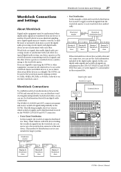
... be used as an audio interface with 16-channel input and output. The 01V96i's remote functionality can also be used to perform locate and transport operations on the DAW, and to a computer-based DAW (Digital Audio Workstation). 26 Connections ... / INSERT/ PAN/ PAIR/ DELAY ROUTING GROUP PATCH DYNAMICS EQ EFFECT FADER MODE VIEW AUX 1 AUX 2 AUX 3 AUX 4 AUX 5 AUX 6 AUX 7 AUX 8 HOME (METER) LAYER 1-16 17-32 MASTER REMOTE OVER 0 -3 -6 -9 -12 -15 -18 -24 -30 -36 -48 STEREO STORE DEC Q HIGH HIGH-MID FREQUENCY LOW-MID GAIN LOW ENTER RECALL SOLO CLEAR...
... be used as an audio interface with 16-channel input and output. The 01V96i's remote functionality can also be used to perform locate and transport operations on the DAW, and to a computer-based DAW (Digital Audio Workstation). 26 Connections ... / INSERT/ PAN/ PAIR/ DELAY ROUTING GROUP PATCH DYNAMICS EQ EFFECT FADER MODE VIEW AUX 1 AUX 2 AUX 3 AUX 4 AUX 5 AUX 6 AUX 7 AUX 8 HOME (METER) LAYER 1-16 17-32 MASTER REMOTE OVER 0 -3 -6 -9 -12 -15 -18 -24 -30 -36 -48 STEREO STORE DEC Q HIGH HIGH-MID FREQUENCY LOW-MID GAIN LOW ENTER RECALL SOLO CLEAR...
Owner's Manual
Page 27
... / INSERT/ PAN/ PAIR/ DELAY ROUTING GROUP PATCH DYNAMICS EQ EFFECT FADER MODE VIEW AUX 1 AUX 2 AUX 3 AUX 4 AUX 5 AUX 6 AUX 7 AUX 8 HOME (METER) LAYER 1-16 17-32 MASTER REMOTE OVER 0 -3 -6 -9 -12 -15 -18 -24 -30 -36 -48 STEREO STORE DEC Q HIGH HIGH-MID FREQUENCY LOW-MID GAIN LOW ENTER RECALL SOLO CLEAR... AUX 8 9 25 BUS 1 10 26 BUS 2 11 27 BUS 3 12 28 BUS 4 13 29 BUS 5 14 30 BUS 6 15 31 BUS 7 16 32 BUS 8 STEREO 01V96i-Owner's Manual The following examples show two ways in the rear panel slot. In this example, the wordclock signal is used as the wordclock...
... / INSERT/ PAN/ PAIR/ DELAY ROUTING GROUP PATCH DYNAMICS EQ EFFECT FADER MODE VIEW AUX 1 AUX 2 AUX 3 AUX 4 AUX 5 AUX 6 AUX 7 AUX 8 HOME (METER) LAYER 1-16 17-32 MASTER REMOTE OVER 0 -3 -6 -9 -12 -15 -18 -24 -30 -36 -48 STEREO STORE DEC Q HIGH HIGH-MID FREQUENCY LOW-MID GAIN LOW ENTER RECALL SOLO CLEAR... AUX 8 9 25 BUS 1 10 26 BUS 2 11 27 BUS 3 12 28 BUS 4 13 29 BUS 5 14 30 BUS 6 15 31 BUS 7 16 32 BUS 8 STEREO 01V96i-Owner's Manual The following examples show two ways in the rear panel slot. In this example, the wordclock signal is used as the wordclock...

Owner's Manual
Page 54
...Grouping Channels & Linking Parameters .......... 59 Grouping & Linking 59 Using Fader Groups and Mute Groups 59 Using Fader Group Master 61 Using Mute Group Master 62 Linking EQ and Compressor Parameters 62 Internal Effects 64 About the Internal Effects 64 Using Effects Processors via Aux Sends... Libraries 75 Remote Control 83 About Remote Function 83 Pro Tools Remote Layer 83 Nuendo/Cubase Remote Layer 93 Other DAW Remote Layer 94 MIDI Remote Layer 94 Machine Control Function 98 MIDI 100 MIDI & the 01V96i 100 MIDI Port Setup 101 Assigning Scenes to Program Changes for Remote...
...Grouping Channels & Linking Parameters .......... 59 Grouping & Linking 59 Using Fader Groups and Mute Groups 59 Using Fader Group Master 61 Using Mute Group Master 62 Linking EQ and Compressor Parameters 62 Internal Effects 64 About the Internal Effects 64 Using Effects Processors via Aux Sends... Libraries 75 Remote Control 83 About Remote Function 83 Pro Tools Remote Layer 83 Nuendo/Cubase Remote Layer 93 Other DAW Remote Layer 94 MIDI Remote Layer 94 Machine Control Function 98 MIDI 100 MIDI & the 01V96i 100 MIDI Port Setup 101 Assigning Scenes to Program Changes for Remote...

Owner's Manual
Page 66
...LAYER Section 13 Layers 21 LEVEL 24 Level controls 12 LEVEL section 45 Lock page 47 Long name 43 LOW button 14 LOW-MID button 14 M MASTER button 13 Master page 23 Metering 23 MIDI button 12 MIDI IN/THRU/OUT ports 17 MIDI indicator 19 MIDI/USB Section 17 mini-YGDAI (Yamaha...Firmware updates 8 FREQUENCY control 14 G G (Gain 36 GAIN control 10, 14 GATE GR 24 H H. 66 Index Index Symbols /INSERT/DELAY button 12 Numerics 01V96i Editor 7 1-16/17-32 buttons 13 1-8 46 1-8 buttons 14 1-8 buttons (Routing 34 2TR IN DIGITAL COAXIAL 17 2TR IN/OUT connectors 11 2TR OUT DIGITAL...
...LAYER Section 13 Layers 21 LEVEL 24 Level controls 12 LEVEL section 45 Lock page 47 Long name 43 LOW button 14 LOW-MID button 14 M MASTER button 13 Master page 23 Metering 23 MIDI button 12 MIDI IN/THRU/OUT ports 17 MIDI indicator 19 MIDI/USB Section 17 mini-YGDAI (Yamaha...Firmware updates 8 FREQUENCY control 14 G G (Gain 36 GAIN control 10, 14 GATE GR 24 H H. 66 Index Index Symbols /INSERT/DELAY button 12 Numerics 01V96i Editor 7 1-16/17-32 buttons 13 1-8 46 1-8 buttons 14 1-8 buttons (Routing 34 2TR IN DIGITAL COAXIAL 17 2TR IN/OUT connectors 11 2TR OUT DIGITAL...
Owner's Manual
Page 67
... 14 Scene Up / Down buttons .........14 SEL buttons 11, 12 SELECTED CHANNEL Section ........14 Selecting Channels 22 Display Pages 20 Fader Modes 22 Layers 21 Setting the Input Levels 32 SHIFT LOCK button 21 Short name 43 Shortcut 46 SIGNAL indicators 10 SLOT Section 18 SOLO buttons 11, 12.............14 UTILITY button 12 Utility software 7 V VIEW button 13 W WAVEFORM 45 WORD CLOCK IN connector 17 WORD CLOCK OUT connector .......17 Wordclock 27 Wordclock master 27 Wordclock slave 27 Wordclock Source 28 Y Yamaha Steinberg USB Driver 7 Index 67 Index 01V96i-Owner's Manual
... 14 Scene Up / Down buttons .........14 SEL buttons 11, 12 SELECTED CHANNEL Section ........14 Selecting Channels 22 Display Pages 20 Fader Modes 22 Layers 21 Setting the Input Levels 32 SHIFT LOCK button 21 Short name 43 Shortcut 46 SIGNAL indicators 10 SLOT Section 18 SOLO buttons 11, 12.............14 UTILITY button 12 Utility software 7 V VIEW button 13 W WAVEFORM 45 WORD CLOCK IN connector 17 WORD CLOCK OUT connector .......17 Wordclock 27 Wordclock master 27 Wordclock slave 27 Wordclock Source 28 Y Yamaha Steinberg USB Driver 7 Index 67 Index 01V96i-Owner's Manual

Reference Manual
Page 2
...Grouping Channels & Linking Parameters .......... 59 Grouping & Linking 59 Using Fader Groups and Mute Groups 59 Using Fader Group Master 61 Using Mute Group Master 62 Linking EQ and Compressor Parameters 62 Internal Effects 64 About the Internal Effects 64 Using Effects Processors via Aux Sends... Libraries 75 Remote Control 83 About Remote Function 83 Pro Tools Remote Layer 83 Nuendo/Cubase Remote Layer 93 Other DAW Remote Layer 94 MIDI Remote Layer 94 Machine Control Function 98 MIDI 100 MIDI & the 01V96i 100 MIDI Port Setup 101 Assigning Scenes to Program Changes for Remote...
...Grouping Channels & Linking Parameters .......... 59 Grouping & Linking 59 Using Fader Groups and Mute Groups 59 Using Fader Group Master 61 Using Mute Group Master 62 Linking EQ and Compressor Parameters 62 Internal Effects 64 About the Internal Effects 64 Using Effects Processors via Aux Sends... Libraries 75 Remote Control 83 About Remote Function 83 Pro Tools Remote Layer 83 Nuendo/Cubase Remote Layer 93 Other DAW Remote Layer 94 MIDI Remote Layer 94 Machine Control Function 98 MIDI 100 MIDI & the 01V96i 100 MIDI Port Setup 101 Assigning Scenes to Program Changes for Remote...

Reference Manual
Page 5
AUX8 HOME (METER) FUNCTION SEND PAN VIEW1-16 VIEW17-STI CH1-32 ST IN MASTER EFFECT STEREO POSITION PAGE NAME LINK AUX1-AUX8 SEND 38 AUX1-AUX8 PAN 41 INPUT CH1-16 AUX VIEW 40 INPUT CH17-ST IN AUX VIEW 40 CH1-32 METER 8 ST IN METER 8 MASTER METER 8 EFFECT1-4 INPUT/OUTPUT METER 8 STEREO METER 8 METER POSITION 8 LAYER BUTTON 1-16 17-32 MASTER REMOTE FUNCTION USER DEFINED ProTools Nuendo Cubase General DAW USER ASSIGNABLE LAYER PAGE NAME LINK 8 8 8 94 83 93 93 94 110 Function Tree 5 01V96i-Reference Manual Function Tree FADER MODE BUTTON AUX1-
AUX8 HOME (METER) FUNCTION SEND PAN VIEW1-16 VIEW17-STI CH1-32 ST IN MASTER EFFECT STEREO POSITION PAGE NAME LINK AUX1-AUX8 SEND 38 AUX1-AUX8 PAN 41 INPUT CH1-16 AUX VIEW 40 INPUT CH17-ST IN AUX VIEW 40 CH1-32 METER 8 ST IN METER 8 MASTER METER 8 EFFECT1-4 INPUT/OUTPUT METER 8 STEREO METER 8 METER POSITION 8 LAYER BUTTON 1-16 17-32 MASTER REMOTE FUNCTION USER DEFINED ProTools Nuendo Cubase General DAW USER ASSIGNABLE LAYER PAGE NAME LINK 8 8 8 94 83 93 93 94 110 Function Tree 5 01V96i-Reference Manual Function Tree FADER MODE BUTTON AUX1-

Reference Manual
Page 6
...OUT PEAK SIGNAL 13 PEAK SIGNAL 14 15 PEAK SIGNAL 16 0 LEVEL10 PHONES DISPLAY ACCESS SCENE MEMORY FADER MODE Section (p. 8) LAYER Section (p. 8) SCENE DIO/SETUP MIDI UTILITY / INSERT/ PAN/ PAIR/ DELAY ROUTING GROUP PATCH DYNAMICS EQ EFFECT FADER MODE VIEW... AUX 1 AUX 2 AUX 3 AUX 4 AUX 5 AUX 6 AUX 7 AUX 8 HOME (METER) LAYER 1-16 17-32 MASTER REMOTE Display Section (p. 9) OVER 0 -3 -6 -9 -12 -15 -18 -24 -30 -36 -48 STEREO STORE DEC Q ... each item, refer to "Control Surface & Rear Panel" in the Owner's Manual. 01V96i-Reference Manual
...OUT PEAK SIGNAL 13 PEAK SIGNAL 14 15 PEAK SIGNAL 16 0 LEVEL10 PHONES DISPLAY ACCESS SCENE MEMORY FADER MODE Section (p. 8) LAYER Section (p. 8) SCENE DIO/SETUP MIDI UTILITY / INSERT/ PAN/ PAIR/ DELAY ROUTING GROUP PATCH DYNAMICS EQ EFFECT FADER MODE VIEW... AUX 1 AUX 2 AUX 3 AUX 4 AUX 5 AUX 6 AUX 7 AUX 8 HOME (METER) LAYER 1-16 17-32 MASTER REMOTE Display Section (p. 9) OVER 0 -3 -6 -9 -12 -15 -18 -24 -30 -36 -48 STEREO STORE DEC Q ... each item, refer to "Control Surface & Rear Panel" in the Owner's Manual. 01V96i-Reference Manual

Reference Manual
Page 8
.../SETUP] button 3 [MIDI] button 4 [UTILITY] button 5 [ /INSERT/DELAY] button 6 [PAN/ROUTING] button 7 [PAIR/GROUP] button 8 [PATCH] button 9 [DYNAMICS] button 0 [EQ] button A [EFFECT] button B [VIEW] button LAYER Section 1 [1-16]/[17-32] buttons 2 [MASTER] button 3 [REMOTE] button LAYER 1-16 17-32 MASTER REMOTE 1 23 Tip: The ST IN section is not affected by the...
.../SETUP] button 3 [MIDI] button 4 [UTILITY] button 5 [ /INSERT/DELAY] button 6 [PAN/ROUTING] button 7 [PAIR/GROUP] button 8 [PATCH] button 9 [DYNAMICS] button 0 [EQ] button A [EFFECT] button B [VIEW] button LAYER Section 1 [1-16]/[17-32] buttons 2 [MASTER] button 3 [REMOTE] button LAYER 1-16 17-32 MASTER REMOTE 1 23 Tip: The ST IN section is not affected by the...

Reference Manual
Page 32
...the [ON] button in the STEREO section. 3 Fader This fader adjusts the Stereo Out output levels, and links with the fader (9-16) in the Master layer. 2 BUS Fader This fader sets the currently-selected Bus Out (1-8) level, and links with the [STEREO] fader. The Fader page layouts for the ...appear on or off , and links with the [ON] (9-16) button in the Master layer. 32 Bus Outs ■ Viewing Faders and Other Parameters To display the View | Fader page, use the corresponding [SEL] button to St page. 01V96i-Reference Manual Stereo Out Fader page 12 Bus Out (1-8) Fader page 12 3 45 3...
...the [ON] button in the STEREO section. 3 Fader This fader adjusts the Stereo Out output levels, and links with the fader (9-16) in the Master layer. 2 BUS Fader This fader sets the currently-selected Bus Out (1-8) level, and links with the [STEREO] fader. The Fader page layouts for the ...appear on or off , and links with the [ON] (9-16) button in the Master layer. 32 Bus Outs ■ Viewing Faders and Other Parameters To display the View | Fader page, use the corresponding [SEL] button to St page. 01V96i-Reference Manual Stereo Out Fader page 12 Bus Out (1-8) Fader page 12 3 45 3...

Reference Manual
Page 33
... in the STEREO section to which you can turn Bus Out 1-8 on or off . Setting the Levels Move the [STEREO] fader to select the Master layer, then move faders 9-16. HIGH-MID band • [L-MID] button .... Press the DISPLAY ACCESS [PAIR/GROUP] button repeatedly until the Pair/Grup | Output ...Out 1-8. Paired bus and Aux Send linked parameters and non-linked parameters (that are available for independent controls) are linked on or off . 01V96i-Reference Manual Press the [ON] button in the LAYER section to adjust the Stereo Out levels. LOW-MID band • [LOW] button .......
... in the STEREO section to which you can turn Bus Out 1-8 on or off . Setting the Levels Move the [STEREO] fader to select the Master layer, then move faders 9-16. HIGH-MID band • [L-MID] button .... Press the DISPLAY ACCESS [PAIR/GROUP] button repeatedly until the Pair/Grup | Output ...Out 1-8. Paired bus and Aux Send linked parameters and non-linked parameters (that are available for independent controls) are linked on or off . 01V96i-Reference Manual Press the [ON] button in the LAYER section to adjust the Stereo Out levels. LOW-MID band • [LOW] button .......

Reference Manual
Page 38
...on the top panel to the Aux selected in Step 1. It links with the corresponding fader (1-8) in the Master layer. • Fader This fader sets the currently-selected Aux Out (1-8) level. tons to select the Master layer, then move faders 1-8. Setting Aux Out 1-8 from each Input Channel to directly control certain parameters for Aux... PRE buttons send pre-fader signals, and the POST buttons send post-fader signals. • MODE Aux Sends have two operating modes that the 01V96i displays the Aux | Send page. It links with the corresponding [ON] (1-8) button in the Master layer.
...on the top panel to the Aux selected in Step 1. It links with the corresponding fader (1-8) in the Master layer. • Fader This fader sets the currently-selected Aux Out (1-8) level. tons to select the Master layer, then move faders 1-8. Setting Aux Out 1-8 from each Input Channel to directly control certain parameters for Aux... PRE buttons send pre-fader signals, and the POST buttons send post-fader signals. • MODE Aux Sends have two operating modes that the 01V96i displays the Aux | Send page. It links with the corresponding [ON] (1-8) button in the Master layer.

Reference Manual
Page 51
...channels by press- The channel [SOLO] button indicators and the SOLO [SOLO] indicator light up. To solo and monitor Output Channels, press the LAYER [MASTER] button, then press the channel [SOLO] buttons. For example, if you solo an Input Channel, then solo an Output Channel, the first ... Tip: If the SEL MODE parameter is cancelled. ing all soloed channels by pressing the SOLO [CLEAR] button. Using the Solo Function 51 01V96i-Reference Manual You can unsolo all illuminated channel [SOLO] buttons. Set the SOLO parameter to Mix Solo on the DIO/Setup | Monitor page, ...
...channels by press- The channel [SOLO] button indicators and the SOLO [SOLO] indicator light up. To solo and monitor Output Channels, press the LAYER [MASTER] button, then press the channel [SOLO] buttons. For example, if you solo an Input Channel, then solo an Output Channel, the first ... Tip: If the SEL MODE parameter is cancelled. ing all soloed channels by pressing the SOLO [CLEAR] button. Using the Solo Function 51 01V96i-Reference Manual You can unsolo all illuminated channel [SOLO] buttons. Set the SOLO parameter to Mix Solo on the DIO/Setup | Monitor page, ...

Reference Manual
Page 65
... In parameter box, select a signal from the effects pro- Tip: Use the Master layer fader to create stereo effects. Press the DISPLAY ACCESS [ /INSERT/DELAY] button repeatedly until the /Ins/Dly | Insert page appears. 01V96i-Reference Manual To select a signal to an IN parameter box and press the [ENTER... parameter to 100% (only the effects sound will return to "Aux Outs" on page 36 for each effect varies depending on the Meter | Master page. 6. Adjust the level of the Input Channels patched to the effects processor's input) on setting the Aux Sends. The Patch Select window ...
... In parameter box, select a signal from the effects pro- Tip: Use the Master layer fader to create stereo effects. Press the DISPLAY ACCESS [ /INSERT/DELAY] button repeatedly until the /Ins/Dly | Insert page appears. 01V96i-Reference Manual To select a signal to an IN parameter box and press the [ENTER... parameter to 100% (only the effects sound will return to "Aux Outs" on page 36 for each effect varies depending on the Meter | Master page. 6. Adjust the level of the Input Channels patched to the effects processor's input) on setting the Aux Sends. The Patch Select window ...

Reference Manual
Page 85
... is set to "Feet:Frames." • BEATS Pro Tools timecode format is set to select Insert Display mode. To control the 01V96i, you need to select an Input Channel Layer or the Master Layer. 5 1 TARGET This parameter enables you to select display modes. The following display modes using these buttons: ■ Insert Display mode...
... is set to "Feet:Frames." • BEATS Pro Tools timecode format is set to select Insert Display mode. To control the 01V96i, you need to select an Input Channel Layer or the Master Layer. 5 1 TARGET This parameter enables you to select display modes. The following display modes using these buttons: ■ Insert Display mode...
