
Installation Instructions
Page 1
.... These installation instructions cover different models. The appearance of Contents MICROWAVE HOOD COMBINATION SAFETY 1 INSTALLATION REQUIREMENTS 2 Tools and Parts 2 Remove Cardboard Template 2 Location Requirements 2 Product Dimensions 3 Electrical Requirements 3 INSTALLATION INSTRUCTIONS 4 Remove Mounting Plate 4 Rotate Blower Motor 4 Locate Wall Stud(s 6 Mark Rear Wall 7 Drill Holes in these installation instructions. We have provided...
.... These installation instructions cover different models. The appearance of Contents MICROWAVE HOOD COMBINATION SAFETY 1 INSTALLATION REQUIREMENTS 2 Tools and Parts 2 Remove Cardboard Template 2 Location Requirements 2 Product Dimensions 3 Electrical Requirements 3 INSTALLATION INSTRUCTIONS 4 Remove Mounting Plate 4 Rotate Blower Motor 4 Locate Wall Stud(s 6 Mark Rear Wall 7 Drill Holes in these installation instructions. We have provided...

Installation Instructions
Page 2
...oven and upper cabinet. ■ Grounded electrical outlet inside the perforation is at least 6" (15.2 cm) of installation. See "Installation Dimensions" illustration. ■ Minimum one 2" x 4" (50.8 x 101.6 mm) wood wall stud and minimum 3/8" (10 mm) ...Requirements Check the opening . ■ Support for wood studs. Special Requirements For Wall Venting Installation Only: ■ Cutout must provide: ■ Minimum installation dimensions. Materials needed ■ Standard fittings for cabinet 1/4-20 x 3" bolts ■ Keyhole saw ■ Drill ■ 3/16" (5 mm), 3/8" (...
...oven and upper cabinet. ■ Grounded electrical outlet inside the perforation is at least 6" (15.2 cm) of installation. See "Installation Dimensions" illustration. ■ Minimum one 2" x 4" (50.8 x 101.6 mm) wood wall stud and minimum 3/8" (10 mm) ...Requirements Check the opening . ■ Support for wood studs. Special Requirements For Wall Venting Installation Only: ■ Cutout must provide: ■ Minimum installation dimensions. Materials needed ■ Standard fittings for cabinet 1/4-20 x 3" bolts ■ Keyhole saw ■ Drill ■ 3/16" (5 mm), 3/8" (...

Installation Instructions
Page 3
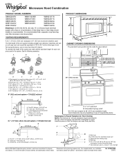
... Requirements WARNING 66" (167.6 cm) min. 30" (76.2 cm) min. 30" (76.2 cm) typical* 12" (30.5 cm) min. 14" (35.6 cm) max. Exact dimensions may vary depending on type of electric shock. In the event of an electrical short circuit, grounding reduces the risk of electric shock by providing... an escape wire for 66" (167.6 cm) installation height. SAVE THESE INSTRUCTIONS 3 Do not use an adapter. Product Dimensions 17¹⁄₄" (43.8 cm) 16¹⁄₄" (41.3 cm) (401.05³c⁄₄m") 29⁷⁄₈" (76.0...
... Requirements WARNING 66" (167.6 cm) min. 30" (76.2 cm) min. 30" (76.2 cm) typical* 12" (30.5 cm) min. 14" (35.6 cm) max. Exact dimensions may vary depending on type of electric shock. In the event of an electrical short circuit, grounding reduces the risk of electric shock by providing... an escape wire for 66" (167.6 cm) installation height. SAVE THESE INSTRUCTIONS 3 Do not use an adapter. Product Dimensions 17¹⁄₄" (43.8 cm) 16¹⁄₄" (41.3 cm) (401.05³c⁄₄m") 29⁷⁄₈" (76.0...

Installation Instructions
Page 7
... 15³⁄₄" (40.0 cm) from the mark made in Step 3, and that the top of the upper cabinet, and must align with the dimensions described in Step 6 of upper cabinet 3. See figures 1, 2 and/or 3 in "Possible Wall Stud Configurations" in "Locate Wall Stud(s)" section. 7 Measure down 4" (10.2 cm) from...
... 15³⁄₄" (40.0 cm) from the mark made in Step 3, and that the top of the upper cabinet, and must align with the dimensions described in Step 6 of upper cabinet 3. See figures 1, 2 and/or 3 in "Possible Wall Stud Configurations" in "Locate Wall Stud(s)" section. 7 Measure down 4" (10.2 cm) from...

Installation Instructions
Page 8
... fits inside the frame, against drywall. Start a toggle nut on the wall. 2. Securely tighten the lag screw(s) and bolt. Make sure the 10" (25.4 cm) dimension from the back of "Installation for Wall Stud at both end holes. 3. With the support tabs of the mounting plate facing forward, insert 1/4-20 x 3" round...
... fits inside the frame, against drywall. Start a toggle nut on the wall. 2. Securely tighten the lag screw(s) and bolt. Make sure the 10" (25.4 cm) dimension from the back of "Installation for Wall Stud at both end holes. 3. With the support tabs of the mounting plate facing forward, insert 1/4-20 x 3" round...
Dimension Guide
Page 1
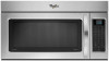
...DIMENSIONS The grounded 3-prong outlet must not exceed the equivalent of vent. Rectangular to round transition piece: 3 " x 10" to 6" = 5 ft (8.3 x 25.4 cm to round transition piece F. Roof cap B. 6" (15.2 cm) min. Vent extension piece, at least 3" (7.6 cm) high Because Whirlpool... for planning purposes only. Microwave Hood Combination PRODUCT MODEL NUMBERS GMH3204XV GMH5205XV GMH6185XV WMH1162XV WMH1163XV WMH1164XW WMH2175XV WMH2205XV WMH3205XV WMH31017A WMH32517A WMH53520A WMH32L19A WMH73L20A Electrical: A 120-Volt, 60-Hz, AC-only, 15- Wall cap: 3 " x 10" = 40 ft (8.3 x ...
...DIMENSIONS The grounded 3-prong outlet must not exceed the equivalent of vent. Rectangular to round transition piece: 3 " x 10" to 6" = 5 ft (8.3 x 25.4 cm to round transition piece F. Roof cap B. 6" (15.2 cm) min. Vent extension piece, at least 3" (7.6 cm) high Because Whirlpool... for planning purposes only. Microwave Hood Combination PRODUCT MODEL NUMBERS GMH3204XV GMH5205XV GMH6185XV WMH1162XV WMH1163XV WMH1164XW WMH2175XV WMH2205XV WMH3205XV WMH31017A WMH32517A WMH53520A WMH32L19A WMH73L20A Electrical: A 120-Volt, 60-Hz, AC-only, 15- Wall cap: 3 " x 10" = 40 ft (8.3 x ...