Dimension Guide
Page 1
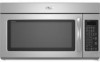
... 90° elbows = 20 ft (6.1 m) B. 1 wall cap = 40 ft (12.2 m) C. 1 rectangular to change without notice. It is recommended that the damper can open freely and fully. Grounded 3-prong outlet *30" (76.2 cm) is recommended. ® Microwave Hood Combination PRODUCT MODEL NUMBERS GMH3204XV GMH5205XV GMH6185XV WMH1162XV WMH1163XV WMH1164XW WMH2175XV WMH2205XV WMH3205XV Electrical: A 120-Volt, 60...
... 90° elbows = 20 ft (6.1 m) B. 1 wall cap = 40 ft (12.2 m) C. 1 rectangular to change without notice. It is recommended that the damper can open freely and fully. Grounded 3-prong outlet *30" (76.2 cm) is recommended. ® Microwave Hood Combination PRODUCT MODEL NUMBERS GMH3204XV GMH5205XV GMH6185XV WMH1162XV WMH1163XV WMH1164XW WMH2175XV WMH2205XV WMH3205XV Electrical: A 120-Volt, 60...

Installation Instructions
Page 1
... manual and on your appliance. This is , tell you how to Wall 8 Prepare Upper Cabinet 8 Install Damper Assembly 9 Install the Microwave Oven 9 Complete Installation 10 VENTING DESIGN SPECIFICATIONS 11 ASSISTANCE 12 Replacement Parts 12 Accessories 12 MICROWAVE HOOD COMBINATION SAFETY Your safety and the safety of injury, and tell you don't follow instructions. These...
... manual and on your appliance. This is , tell you how to Wall 8 Prepare Upper Cabinet 8 Install Damper Assembly 9 Install the Microwave Oven 9 Complete Installation 10 VENTING DESIGN SPECIFICATIONS 11 ASSISTANCE 12 Replacement Parts 12 Accessories 12 MICROWAVE HOOD COMBINATION SAFETY Your safety and the safety of injury, and tell you don't follow instructions. These...

Installation Instructions
Page 2
... screws ■ Scissors ■ 1½" (3.8 cm) diam. The location must be free of wall structures, be combined. See "Rectangular to make sure there is at least 6" (15.2 cm) of installation. For other damages. NOTES: ■ If installing the microwave oven near a left sidewall, make sure that the vent fits properly, and the damper...
... screws ■ Scissors ■ 1½" (3.8 cm) diam. The location must be free of wall structures, be combined. See "Rectangular to make sure there is at least 6" (15.2 cm) of installation. For other damages. NOTES: ■ If installing the microwave oven near a left sidewall, make sure that the vent fits properly, and the damper...

Installation Instructions
Page 3
...max. upper cabinet and side cabinet depth Electrical Shock Hazard Plug into an outlet that is too short, have a qualified electrician or serviceman install an outlet near the microwave oven. Recommended: ■ A time-delay fuse or time-delay circuit breaker. ■ A separate circuit ...serving only this microwave oven. If the power supply cord is properly installed and grounded. The plug must be plugged into a grounded 3 prong outlet. Do not use an adapter. Do not use an extension cord. ...
...max. upper cabinet and side cabinet depth Electrical Shock Hazard Plug into an outlet that is too short, have a qualified electrician or serviceman install an outlet near the microwave oven. Recommended: ■ A time-delay fuse or time-delay circuit breaker. ■ A separate circuit ...serving only this microwave oven. If the power supply cord is properly installed and grounded. The plug must be plugged into a grounded 3 prong outlet. Do not use an adapter. Do not use an extension cord. ...

Installation Instructions
Page 4
... A. NOTE: To avoid possible damage to the venting system. Remove 2 screws attaching blower motor to top of microwave oven. Damper plate B. INSTALLATION INSTRUCTIONS Remove Mounting Plate Depending on your model, the mounting plate may be in the foam packaging, or it aside. 3. Damper plate 2. ...or use the door or door handle while the microwave oven is being handled. 4. Make sure damper plate tabs are using recirculation installation. Slots 8. Remove any remaining contents from the microwave oven cavity. 2. NOTE: To avoid damage to back of the microwave oven....
... A. NOTE: To avoid possible damage to the venting system. Remove 2 screws attaching blower motor to top of microwave oven. Damper plate B. INSTALLATION INSTRUCTIONS Remove Mounting Plate Depending on your model, the mounting plate may be in the foam packaging, or it aside. 3. Damper plate 2. ...or use the door or door handle while the microwave oven is being handled. 4. Make sure damper plate tabs are using recirculation installation. Slots 8. Remove any remaining contents from the microwave oven cavity. 2. NOTE: To avoid damage to back of the microwave oven....

Installation Instructions
Page 5
...screws removed in the top of "Wall Venting Installation Only." 5 Screws C. Roof Venting Installation Only 1. Repeat Step 4 from "Wall Venting Installation Only." 3. Repeat Step 2 from "Wall Venting Installation Only." 5. Repeat Step 3 from "Wall Venting Installation Only." 2. Lower blower motor back into the...Step 3 cannot be poor. Securely tighten screws. Damper plate B. Damper plate tabs D. Repeat Step 1 from "Wall Venting Installation Only." 4. Reattach damper plate. Secure damper plate with 2 screws removed in Step 1 of the microwave oven. Rotate blower ...
...screws removed in the top of "Wall Venting Installation Only." 5 Screws C. Roof Venting Installation Only 1. Repeat Step 4 from "Wall Venting Installation Only." 3. Repeat Step 2 from "Wall Venting Installation Only." 5. Repeat Step 3 from "Wall Venting Installation Only." 2. Lower blower motor back into the...Step 3 cannot be poor. Securely tighten screws. Damper plate B. Damper plate tabs D. Repeat Step 1 from "Wall Venting Installation Only." 4. Reattach damper plate. Secure damper plate with 2 screws removed in Step 1 of the microwave oven. Rotate blower ...

Installation Instructions
Page 6
End holes (on mounting plate) B. Support tabs F. Cabinet opening , do not install the microwave oven. 1. Locate Wall Stud(s) NOTE: If no wall studs exist within 6" (15.2 cm) of each stud, and draw a plumb line down each stud ... wall stud is within the cabinet opening vertical centerline C. Mounting plate center markers 6 Holes for lag screws E. Using a stud finder, locate the edges of preferred installation configurations with the mounting plate. Mark the center of the vertical centerline (see "Mark Rear Wall" section), only recirculation or roof venting...
End holes (on mounting plate) B. Support tabs F. Cabinet opening , do not install the microwave oven. 1. Locate Wall Stud(s) NOTE: If no wall studs exist within 6" (15.2 cm) of each stud, and draw a plumb line down each stud ... wall stud is within the cabinet opening vertical centerline C. Mounting plate center markers 6 Holes for lag screws E. Using a stud finder, locate the edges of preferred installation configurations with the mounting plate. Mark the center of the vertical centerline (see "Mark Rear Wall" section), only recirculation or roof venting...

Installation Instructions
Page 7
... preferably 2, using a minimum of 1 lag screw, preferably 2. 1. Make sure the mounting plate is the venting cutout area. 13. Set the mounting plate aside. Wall Venting Installation Only Upper cabinet bottom ³⁄₈" (1 cm) 4" (10.2 cm) Centerline 6" (15.2 cm) 6" (15.2 cm) 8. This is level. 6. if ...1 end hole is damaged or unusable, measure and mark the wall with the dimensions described in Step 3 of the upper cabinet. Installation for No Wall Studs at both sides of "Locate Wall Stud(s)," and mark at least 1 wall stud, the mounting plate must attach to ...
... preferably 2, using a minimum of 1 lag screw, preferably 2. 1. Make sure the mounting plate is the venting cutout area. 13. Set the mounting plate aside. Wall Venting Installation Only Upper cabinet bottom ³⁄₈" (1 cm) 4" (10.2 cm) Centerline 6" (15.2 cm) 6" (15.2 cm) 8. This is level. 6. if ...1 end hole is damaged or unusable, measure and mark the wall with the dimensions described in Step 3 of the upper cabinet. Installation for No Wall Studs at both sides of "Locate Wall Stud(s)," and mark at least 1 wall stud, the mounting plate must attach to ...

Installation Instructions
Page 8
...the frame, against drywall. 5. Make sure the template centerline aligns with toggle nuts through both end holes drilled into the remaining end hole. 6. Installation for Wall Stud at One End Hole (Figure 3) 1. Start toggle nuts on a second wall stud, drill a 3/16" (5 mm) hole ...into both ends. 1. Check alignment of "Mark Rear Wall." Mounting plate C. Installation for Wall Studs at Both End Holes (Figure 4) 1. Drill 3/16" (5 mm) holes into the upper cabinet align with tape or thumbtacks. C A 6. With...
...the frame, against drywall. 5. Make sure the template centerline aligns with toggle nuts through both end holes drilled into the remaining end hole. 6. Installation for Wall Stud at One End Hole (Figure 3) 1. Start toggle nuts on a second wall stud, drill a 3/16" (5 mm) hole ...into both ends. 1. Check alignment of "Mark Rear Wall." Mounting plate C. Installation for Wall Studs at Both End Holes (Figure 4) 1. Drill 3/16" (5 mm) holes into the upper cabinet align with tape or thumbtacks. C A 6. With...

Installation Instructions
Page 9
...template. Place a washer on the template. Mounting plate B. Power supply cord bushing 6. IMPORTANT: The control side of microwave oven B. For Roof Venting Installation Only 7. Cut the 1¹⁄₂" (3.8 cm) diameter hole at points "D" and "E" on each 1/4-20 x 3" flat-head bolt and... one corner of the upper cabinet. 5. Rotate microwave oven up toward upper cabinet. Support tabs 4. Metal cabinet B. A B C D Install the Microwave Oven WARNING Excessive Weight Hazard Use two or more people, lift microwave oven and hang it on the back of mounting plate. ...
...template. Place a washer on the template. Mounting plate B. Power supply cord bushing 6. IMPORTANT: The control side of microwave oven B. For Roof Venting Installation Only 7. Cut the 1¹⁄₂" (3.8 cm) diameter hole at points "D" and "E" on each 1/4-20 x 3" flat-head bolt and... one corner of the upper cabinet. 5. Rotate microwave oven up toward upper cabinet. Support tabs 4. Metal cabinet B. A B C D Install the Microwave Oven WARNING Excessive Weight Hazard Use two or more people, lift microwave oven and hang it on the back of mounting plate. ...

Installation Instructions
Page 10
...the problem continues, call an electrician. ■ Check that the long tab of the damper assembly slides under vent) Complete Installation 1. Save Installation Instructions for future use an extension cord. Repeat steps 3-6. 10. Damper assembly (under the raised tabs of the damper ... skip steps 7-9. 7. Sheet metal screw D. Adjust mounting plate and retighten screws. 9. Damper assembly C. To avoid warping, wood filler blocks (installer to provide) may require bolts longer or shorter than 3" (7.6 cm). A 2. Then secure with at most hardware stores. ■ Overtightening ...
...the problem continues, call an electrician. ■ Check that the long tab of the damper assembly slides under vent) Complete Installation 1. Save Installation Instructions for future use an extension cord. Repeat steps 3-6. 10. Damper assembly (under the raised tabs of the damper ... skip steps 7-9. 7. Sheet metal screw D. Adjust mounting plate and retighten screws. 9. Damper assembly C. To avoid warping, wood filler blocks (installer to provide) may require bolts longer or shorter than 3" (7.6 cm). A 2. Then secure with at most hardware stores. ■ Overtightening ...

Installation Instructions
Page 11
...be sure there is at least 3" (7.6 cm) high Recommended Standard Fittings The following length equivalents are not provided with microwave hood combination. ■ We do not recommend using a flexible metal vent. ■ To avoid possible product damage, be sure to vent...10" = 40 ft (8.3 x 25.4 cm = 12.2 m) F. 45° elbow: 6" = 5 ft (15.2 cm = 1.5 m) G. 90° flat elbow: 3¹⁄₄" x 10" = 10 ft (8.3 x 25.4 cm = 3 m) 11 VENTING DESIGN SPECIFICATIONS This section is intended for wall venting only) D. NOTES: ■ Vent materials needed for installation are for the...
...be sure there is at least 3" (7.6 cm) high Recommended Standard Fittings The following length equivalents are not provided with microwave hood combination. ■ We do not recommend using a flexible metal vent. ■ To avoid possible product damage, be sure to vent...10" = 40 ft (8.3 x 25.4 cm = 12.2 m) F. 45° elbow: 6" = 5 ft (15.2 cm = 1.5 m) G. 90° flat elbow: 3¹⁄₄" x 10" = 10 ft (8.3 x 25.4 cm = 3 m) 11 VENTING DESIGN SPECIFICATIONS This section is intended for wall venting only) D. NOTES: ■ Vent materials needed for installation are for the...

Installation Instructions
Page 12
... piece used . W10247296B SP PN W10345003B © 2010. See the following examples: 3¹⁄₄" x 10" (8.3 x 25.4 cm) vent system = 73 ft (22.2 m) total A B 6 ft (1.8 m) 2 ft (0.6 m) C A. Replacement Parts If any of the installation hardware needs to be replaced, call , you need your dealer to round transition piece must not exceed the equivalent of 140...
... piece used . W10247296B SP PN W10345003B © 2010. See the following examples: 3¹⁄₄" x 10" (8.3 x 25.4 cm) vent system = 73 ft (22.2 m) total A B 6 ft (1.8 m) 2 ft (0.6 m) C A. Replacement Parts If any of the installation hardware needs to be replaced, call , you need your dealer to round transition piece must not exceed the equivalent of 140...
Owners Manual
Page 1
... horno de microondas, detrás de la puerta. Microwave Hood Combination Safety Your safety and the safety of burns, electric shock, fire, injury to persons, or exposure to excessive microwave energy: ■ Install or locate the microwave oven only in this manual and on your...injured if you how to properly grounded outlet. You will follow instructions. All safety messages will need assistance, call us at www.whirlpool.com for example, closed glass jars - for additional information. SAVE THESE INSTRUCTIONS W10208075A WARNING You can happen if the instructions are very...
... horno de microondas, detrás de la puerta. Microwave Hood Combination Safety Your safety and the safety of burns, electric shock, fire, injury to persons, or exposure to excessive microwave energy: ■ Install or locate the microwave oven only in this manual and on your...injured if you how to properly grounded outlet. You will follow instructions. All safety messages will need assistance, call us at www.whirlpool.com for example, closed glass jars - for additional information. SAVE THESE INSTRUCTIONS W10208075A WARNING You can happen if the instructions are very...
Owners Manual
Page 3
... the filters. Touch the Options or Setup control to unlock control. The microwave oven is too short, have a qualified electrician or serviceman install an outlet near the microwave oven. Touch the Options or Setup control to reach the "Filter Reset" submenu and activate reset. Do not...enter time, then touch the Timer control or the Start control. Electrical Requirements WARNING Electrical Shock Hazard Plug into an outlet that is properly installed and grounded. The vent fan may be changed. Touch Options or Setup control to reach the "Demo Mode" submenu, and activate or ...
... the filters. Touch the Options or Setup control to unlock control. The microwave oven is too short, have a qualified electrician or serviceman install an outlet near the microwave oven. Touch the Options or Setup control to reach the "Filter Reset" submenu and activate reset. Do not...enter time, then touch the Timer control or the Start control. Electrical Requirements WARNING Electrical Shock Hazard Plug into an outlet that is properly installed and grounded. The vent fan may be changed. Touch Options or Setup control to reach the "Demo Mode" submenu, and activate or ...
Owners Manual
Page 6
... cover, cooking rack supports, and area where the door touches the frame can cause arcing. Installing/Replacing Filters and Light Bulbs NOTE: A filter status indicator (on the underside of the microwave oven, and is off . www.whirlpool.com Microwave oven will dissipate with screws. ■ Cooktop light: The cooktop light is located...
... cover, cooking rack supports, and area where the door touches the frame can cause arcing. Installing/Replacing Filters and Light Bulbs NOTE: A filter status indicator (on the underside of the microwave oven, and is off . www.whirlpool.com Microwave oven will dissipate with screws. ■ Cooktop light: The cooktop light is located...
Owners Manual
Page 8
...SHORTEST PERIOD ALLOWED BY LAW. W10208075A SP PN W10208079A © 2008 Whirlpool Corporation. Proof of the microwave oven opening, behind the door. This major appliance is not installed in accordance with original model/serial numbers that is operated and maintained ...information for other damage to correct defects in materials or workmanship and is covered by an authorized Whirlpool servicer is not available. 10. Major appliances with published installation instructions. 11. Repairs when your major appliance is required to correct house wiring or plumbing....
...SHORTEST PERIOD ALLOWED BY LAW. W10208075A SP PN W10208079A © 2008 Whirlpool Corporation. Proof of the microwave oven opening, behind the door. This major appliance is not installed in accordance with original model/serial numbers that is operated and maintained ...information for other damage to correct defects in materials or workmanship and is covered by an authorized Whirlpool servicer is not available. 10. Major appliances with published installation instructions. 11. Repairs when your major appliance is required to correct house wiring or plumbing....

Warranty
Page 1
... and model number information for product service if your major appliance if it is installed in an inaccessible location or is not installed in materials or workmanship and is reported to Whirlpool within 30 days from the date of purchase, when this warranty. 8. Costs ...associated with the product, Whirlpool Corporation or Whirlpool Canada LP (hereafter "Whirlpool") will pay for Factory Specified Parts...
... and model number information for product service if your major appliance if it is installed in an inaccessible location or is not installed in materials or workmanship and is reported to Whirlpool within 30 days from the date of purchase, when this warranty. 8. Costs ...associated with the product, Whirlpool Corporation or Whirlpool Canada LP (hereafter "Whirlpool") will pay for Factory Specified Parts...


