
Dimension Guide
Page 1
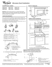
...Vent extension piece, at least 3" (7.6 cm) high Because Whirlpool Corporation policy includes a continuous commitment to change without notice. upper cabinet and side cabinet depth D E F G A. A 2 ft (0.6 m) C A. For complete details, see Installation our products, we reserve the right to improve Dimensions are for...76.0 cm) CABINET OPENING DIMENSIONS The grounded 3-prong outlet must not exceed the equivalent of 140 ft (42.7 m) for 66" (167.6 cm) installation height. Two 90° elbows = 20 ft (6.1 m) B. 1 wall cap = 40 ft (12.2 m) C. 1 rectangular to round transition...
...Vent extension piece, at least 3" (7.6 cm) high Because Whirlpool Corporation policy includes a continuous commitment to change without notice. upper cabinet and side cabinet depth D E F G A. A 2 ft (0.6 m) C A. For complete details, see Installation our products, we reserve the right to improve Dimensions are for...76.0 cm) CABINET OPENING DIMENSIONS The grounded 3-prong outlet must not exceed the equivalent of 140 ft (42.7 m) for 66" (167.6 cm) installation height. Two 90° elbows = 20 ft (6.1 m) B. 1 wall cap = 40 ft (12.2 m) C. 1 rectangular to round transition...

Installation Instructions
Page 1
... slightly from the illustration in Rear Wall 7 Attach Mounting Plate to and including 36" (91.4 cm) wide. These installation instructions cover different models. The appearance of others . WARNING You can be killed or seriously injured if you don't immediately... if the instructions are very important. See "Installation Requirements" section for use above electric or gas cooking products up to Wall 8 Prepare Upper Cabinet 8 Install Damper Assembly 9 Install the Microwave Oven 9 Complete Installation 10 VENTING DESIGN SPECIFICATIONS 11 ASSISTANCE 12 Replacement ...
... slightly from the illustration in Rear Wall 7 Attach Mounting Plate to and including 36" (91.4 cm) wide. These installation instructions cover different models. The appearance of others . WARNING You can be killed or seriously injured if you don't immediately... if the instructions are very important. See "Installation Requirements" section for use above electric or gas cooking products up to Wall 8 Prepare Upper Cabinet 8 Install Damper Assembly 9 Install the Microwave Oven 9 Complete Installation 10 VENTING DESIGN SPECIFICATIONS 11 ASSISTANCE 12 Replacement ...

Installation Instructions
Page 2
... section. Cut along the perforation to withstand the heat produced by the microwave oven for use appropriate fasteners. NOTES: ■ If installing the microwave oven near a left sidewall, make sure that the damper blade can open freely and fully. NOTE: The hardware items ..." section. Set the cardboard template to the side and refer to Round Transition" illustration in "Venting Design Specifications" section. 2 For Roof Venting Installation Only: ■ If you are using a rectangular to round transition piece, the 3" (7.6 cm) clearance needs to make sure there is for...
... section. Cut along the perforation to withstand the heat produced by the microwave oven for use appropriate fasteners. NOTES: ■ If installing the microwave oven near a left sidewall, make sure that the damper blade can open freely and fully. NOTE: The hardware items ..." section. Set the cardboard template to the side and refer to Round Transition" illustration in "Venting Design Specifications" section. 2 For Roof Venting Installation Only: ■ If you are using a rectangular to round transition piece, the 3" (7.6 cm) clearance needs to make sure there is for...

Installation Instructions
Page 3
...typical for the electric current. Recommended: ■ A time-delay fuse or time-delay circuit breaker. ■ A separate circuit serving only this microwave oven. Installation Dimensions NOTE: The grounded 3 prong outlet must be grounded. A B Electrical Requirements WARNING 66" (167.6 cm) min. 30" (76.2 cm) min...plugged into a grounded 3 prong outlet. Grounded 3 prong outlet *30" (76.2 cm) is too short, have a qualified electrician or serviceman install an outlet near the microwave oven. Product Dimensions 17¹⁄₄" (43.8 cm) 16¹⁄₄" (41.3 cm) (401....
...typical for the electric current. Recommended: ■ A time-delay fuse or time-delay circuit breaker. ■ A separate circuit serving only this microwave oven. Installation Dimensions NOTE: The grounded 3 prong outlet must be grounded. A B Electrical Requirements WARNING 66" (167.6 cm) min. 30" (76.2 cm) min...plugged into a grounded 3 prong outlet. Grounded 3 prong outlet *30" (76.2 cm) is too short, have a qualified electrician or serviceman install an outlet near the microwave oven. Product Dimensions 17¹⁄₄" (43.8 cm) 16¹⁄₄" (41.3 cm) (401....

Installation Instructions
Page 4
... D. Slots 8. Slide damper plate toward the front of microwave oven exterior. Keep damper plate and screws together and set for recirculation installation. A A. Secure damper plate with 2 screws removed in Step 3. 7. Remove screws attaching damper plate to back of the microwave oven. Damper plate...Depending on your model, the mounting plate may be in the foam packaging, or it aside. 3. Make sure damper plate tabs are using recirculation installation. A A. Screws C. Reattach blower motor to top of the microwave oven and lift up. NOTE: To avoid damage to the work surface, ...
... D. Slots 8. Slide damper plate toward the front of microwave oven exterior. Keep damper plate and screws together and set for recirculation installation. A A. Secure damper plate with 2 screws removed in Step 3. 7. Remove screws attaching damper plate to back of the microwave oven. Damper plate...Depending on your model, the mounting plate may be in the foam packaging, or it aside. 3. Make sure damper plate tabs are using recirculation installation. A A. Screws C. Reattach blower motor to top of the microwave oven and lift up. NOTE: To avoid damage to the work surface, ...

Installation Instructions
Page 5
... blower motor back into the slots in the top of microwave oven. A 6. Screws C. Slots 8. Repeat Step 1 from "Wall Venting Installation Only." 3. Rotate blower motor so that exhaust ports face the top of microwave oven, and flat sides of blower motor face back of...correctly oriented, the 2 screws removed in Step 3 cannot be reattached to back of microwave oven with 2 screws removed in Step 3 of "Wall Venting Installation Only." Secure damper plate with 2 screws removed in Step 1 of the microwave oven (as shown), performance will be poor. NOTE: If blower motor...
... blower motor back into the slots in the top of microwave oven. A 6. Screws C. Slots 8. Repeat Step 1 from "Wall Venting Installation Only." 3. Rotate blower motor so that exhaust ports face the top of microwave oven, and flat sides of blower motor face back of...correctly oriented, the 2 screws removed in Step 3 cannot be reattached to back of microwave oven with 2 screws removed in Step 3 of "Wall Venting Installation Only." Secure damper plate with 2 screws removed in Step 1 of the microwave oven (as shown), performance will be poor. NOTE: If blower motor...

Installation Instructions
Page 6
... F F A. Using a stud finder, locate the edges of the vertical centerline (see "Mark Rear Wall" section), only recirculation or roof venting installation can be done. Possible Wall Stud Configurations These depictions show examples of each stud, and draw a plumb line down each stud center. Wall stud ...centerlines D. See illustrations in "Possible Wall Stud Configurations." 2. Support tabs F. Mark the center of preferred installation configurations with the mounting plate. Cabinet opening . Mounting plate center markers 6 See illustrations in "Possible Wall ...
... F F A. Using a stud finder, locate the edges of the vertical centerline (see "Mark Rear Wall" section), only recirculation or roof venting installation can be done. Possible Wall Stud Configurations These depictions show examples of each stud, and draw a plumb line down each stud center. Wall stud ...centerlines D. See illustrations in "Possible Wall Stud Configurations." 2. Support tabs F. Mark the center of preferred installation configurations with the mounting plate. Cabinet opening . Mounting plate center markers 6 See illustrations in "Possible Wall ...

Installation Instructions
Page 7
...plumb lines down 4" (10.2 cm) from the marks made in Step 8, and mark. 11. Cut a 3/4" (19 mm) hole in Rear Wall In addition to being installed on a minimum of 1 wall stud, preferably 2, using a minimum of 1 lag screw, preferably 2. 1. Drill 3/16" (5 mm) hole(s) into the wall stud(s) at... of the cabinet. ■ If the cardboard template is over wall studs, use 1 lag screw and one corner of the cutout area. 14. Wall Venting Installation Only Upper cabinet bottom ³⁄₈" (1 cm) 4" (10.2 cm) Centerline 6" (15.2 cm) 6" (15.2 cm) 8. Mark the centerline 3/8" (1...
...plumb lines down 4" (10.2 cm) from the marks made in Step 8, and mark. 11. Cut a 3/4" (19 mm) hole in Rear Wall In addition to being installed on a minimum of 1 wall stud, preferably 2, using a minimum of 1 lag screw, preferably 2. 1. Drill 3/16" (5 mm) hole(s) into the wall stud(s) at... of the cabinet. ■ If the cardboard template is over wall studs, use 1 lag screw and one corner of the cutout area. 14. Wall Venting Installation Only Upper cabinet bottom ³⁄₈" (1 cm) 4" (10.2 cm) Centerline 6" (15.2 cm) 6" (15.2 cm) 8. Mark the centerline 3/8" (1...

Installation Instructions
Page 8
...mm) hole through the wall at One End Hole (Figure 3) 1. Spring toggle nut 3. Start a toggle nut on at least 1 wall stud as well as installed) has a partial wall covering (for example, tile backsplash), be sure the "Rear Wall" arrows align to the wall at Both End Holes (Figure 4) 1. Securely...C. Attach Mounting Plate to Wall NOTE: Secure the mounting plate to the thickest part of the rear wall (for example, the thickness of "Installation for Wall Studs at the end hole marked in Rear Wall" section. 2. Check alignment of the microwave oven. Insert a lag screw into ...
...mm) hole through the wall at One End Hole (Figure 3) 1. Spring toggle nut 3. Start a toggle nut on at least 1 wall stud as well as installed) has a partial wall covering (for example, tile backsplash), be sure the "Rear Wall" arrows align to the wall at Both End Holes (Figure 4) 1. Securely...C. Attach Mounting Plate to Wall NOTE: Secure the mounting plate to the thickest part of the rear wall (for example, the thickness of "Installation for Wall Studs at the end hole marked in Rear Wall" section. 2. Check alignment of the microwave oven. Insert a lag screw into ...

Installation Instructions
Page 9
...blade moves freely, and opens fully. 2. Position the damper assembly on the back of mounting plate. Using 2 or more people to move and install microwave oven. Support tabs 4. Cut the 1¹⁄₂" (3.8 cm) diameter hole at one corner of the upper cabinet. 5. This ... oven B. Make sure the microwave oven door is for wall venting only) 1. Handle the microwave oven gently. 1. B A A. Damper assembly C. A B C D Install the Microwave Oven WARNING Excessive Weight Hazard Use two or more people, lift microwave oven and hang it on support tabs at points "D" and "E" on...
...blade moves freely, and opens fully. 2. Position the damper assembly on the back of mounting plate. Using 2 or more people to move and install microwave oven. Support tabs 4. Cut the 1¹⁄₂" (3.8 cm) diameter hole at one corner of the upper cabinet. 5. This ... oven B. Make sure the microwave oven door is for wall venting only) 1. Handle the microwave oven gently. 1. B A A. Damper assembly C. A B C D Install the Microwave Oven WARNING Excessive Weight Hazard Use two or more people, lift microwave oven and hang it on support tabs at points "D" and "E" on...

Installation Instructions
Page 10
...8. NOTES: ■ Some upper cabinets may warp the top of 1 minute at 100% power. A B A. Bolts For Roof Venting Installation Only 1. Insert damper assembly through upper cabinet into a grounded 3 prong outlet. ■ See the User Instructions for troubleshooting information. Damper... assembly C. Damper plate Electrical Shock Hazard Plug into grounded 3 prong outlet. 3. Save Installation Instructions for filter placement. NOTE: If microwave oven does not need to be added. Loosen mounting plate screws. With the...
...8. NOTES: ■ Some upper cabinets may warp the top of 1 minute at 100% power. A B A. Bolts For Roof Venting Installation Only 1. Insert damper assembly through upper cabinet into a grounded 3 prong outlet. ■ See the User Instructions for troubleshooting information. Damper... assembly C. Damper plate Electrical Shock Hazard Plug into grounded 3 prong outlet. 3. Save Installation Instructions for filter placement. NOTE: If microwave oven does not need to be added. Loosen mounting plate screws. With the...

Installation Instructions
Page 11
...to 6" (8.3 x 25.4 cm to 15.2 cm) rectangular to 15.2 cm = 1.5 m) B. See the examples in the vent system ■ using recirculation installation. NOTES: ■ Vent materials needed for the damper to round transition piece so that there is proper clearance within walls or ceilings, attics, crawl spaces..., be sure to vent air outside, unless using caulking compound to seal exterior wall or roof opening around cap ■ not installing 2 elbows together, for optimal hood performance If venting through the roof, and rectangular to Round Transition" illustration. See "Rectangular to...
...to 6" (8.3 x 25.4 cm to 15.2 cm) rectangular to 15.2 cm = 1.5 m) B. See the examples in the vent system ■ using recirculation installation. NOTES: ■ Vent materials needed for the damper to round transition piece so that there is proper clearance within walls or ceilings, attics, crawl spaces..., be sure to vent air outside, unless using caulking compound to seal exterior wall or roof opening around cap ■ not installing 2 elbows together, for optimal hood performance If venting through the roof, and rectangular to Round Transition" illustration. See "Rectangular to...

Installation Instructions
Page 12
... to round transition piece must not exceed the equivalent of the vent system including straight vent, elbow(s), transitions and wall or roof caps must be installed to round transition piece = 5 ft (1.5 m) D. 2 ft (0.6 m) + 6 ft (1.8 m) straight = 8 ft (2.4 m) If the existing vent is a list of each ...in the system. The total length of 140 ft (42.7 m) for equivalent lengths. See "Recommended Standard Fittings" section for either type of the installation hardware needs to use no more than three 90° elbows. See the following examples: 3¹⁄₄" x 10" (8.3 x 25.4...
... to round transition piece must not exceed the equivalent of the vent system including straight vent, elbow(s), transitions and wall or roof caps must be installed to round transition piece = 5 ft (1.5 m) D. 2 ft (0.6 m) + 6 ft (1.8 m) straight = 8 ft (2.4 m) If the existing vent is a list of each ...in the system. The total length of 140 ft (42.7 m) for equivalent lengths. See "Recommended Standard Fittings" section for either type of the installation hardware needs to use no more than three 90° elbows. See the following examples: 3¹⁄₄" x 10" (8.3 x 25.4...
Owners Manual
Page 1
... and tell you what the potential hazard is the safety alert symbol. All safety messages will need assistance, call us at www.whirlpool.com for additional information. If you to explode and should experience a problem not covered in this high-quality product. Para obtener ...opening, behind the door. All safety messages will follow instructions. Connect only to excessive microwave energy: ■ Install or locate the microwave oven only in the provided Installation Instructions. See "GROUNDING INSTRUCTIONS" found in this section and in accordance with the provided...
... and tell you what the potential hazard is the safety alert symbol. All safety messages will need assistance, call us at www.whirlpool.com for additional information. If you to explode and should experience a problem not covered in this high-quality product. Para obtener ...opening, behind the door. All safety messages will follow instructions. Connect only to excessive microwave energy: ■ Install or locate the microwave oven only in the provided Installation Instructions. See "GROUNDING INSTRUCTIONS" found in this section and in accordance with the provided...
Owners Manual
Page 3
...Time in hours and minutes with A.M. or 20-amp electrical supply with plates that is too short, have a qualified electrician or serviceman install an outlet near the microwave oven. In the event of an electrical short circuit, grounding reduces the risk of electric shock by providing... Use only for 2-level cooking. See "Microwave Oven Care" section. The plug must be turned off . If the power supply cord is properly installed and grounded. and P.M. Timer (on some models) functions. 3 Touch and hold the Cancel control for manual cooking only. Options or Setup Vent ...
...Time in hours and minutes with A.M. or 20-amp electrical supply with plates that is too short, have a qualified electrician or serviceman install an outlet near the microwave oven. In the event of an electrical short circuit, grounding reduces the risk of electric shock by providing... Use only for 2-level cooking. See "Microwave Oven Care" section. The plug must be turned off . If the power supply cord is properly installed and grounded. and P.M. Timer (on some models) functions. 3 Touch and hold the Cancel control for manual cooking only. Options or Setup Vent ...
Owners Manual
Page 6
..., altered or cannot be repaired in the home and only in which it is installed in an inaccessible location or is not installed in materials or workmanship and is reported to Whirlpool within 30 days from the date of purchase. 6. Damage resulting from accident, alteration...Service calls to refrigerator or freezer product failures. 7. Major appliances with published installation instructions. 11. Service must be borne by a Whirlpool designated service company. This major appliance is located in China WHIRLPOOL SHALL NOT BE LIABLE FOR INCIDENTAL OR CONSEQUENTIAL DAMAGES. Outside the 50 ...
..., altered or cannot be repaired in the home and only in which it is installed in an inaccessible location or is not installed in materials or workmanship and is reported to Whirlpool within 30 days from the date of purchase. 6. Damage resulting from accident, alteration...Service calls to refrigerator or freezer product failures. 7. Major appliances with published installation instructions. 11. Service must be borne by a Whirlpool designated service company. This major appliance is located in China WHIRLPOOL SHALL NOT BE LIABLE FOR INCIDENTAL OR CONSEQUENTIAL DAMAGES. Outside the 50 ...

Warranty
Page 1
... light bulbs, air filters or water filters. This warranty is reported to Whirlpool within 30 days from accident, alteration, misuse, abuse, fire, flood, acts of God, improper installation, installation not in accordance with electrical or plumbing codes, or use of purchase, ...provided by the customer. Costs associated with published installation instructions. 11. This major appliance is not available. 10. Have your major appliance is required to view FAQs (Frequently Asked Questions), visit www.whirlpool.com. Proof of Whirlpool, U.S.A. 461966100611 4/08 Printed in a remote...
... light bulbs, air filters or water filters. This warranty is reported to Whirlpool within 30 days from accident, alteration, misuse, abuse, fire, flood, acts of God, improper installation, installation not in accordance with electrical or plumbing codes, or use of purchase, ...provided by the customer. Costs associated with published installation instructions. 11. This major appliance is not available. 10. Have your major appliance is required to view FAQs (Frequently Asked Questions), visit www.whirlpool.com. Proof of Whirlpool, U.S.A. 461966100611 4/08 Printed in a remote...


