Dimension Guide
Page 1
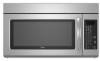
... total A B 6 ft (1.8 m) A. 2" x 4" wall stud B. Rectangular to change without notice. For complete details, see Installation our products, we reserve the right to Round Transition for either type of vent. Specifications subject to round transition piece so that a ...) min. ® Microwave Hood Combination PRODUCT MODEL NUMBERS GMH3204XV GMH5205XV GMH6185XV WMH1162XV WMH1163XV WMH1164XW WMH2175XV WMH2205XV WMH3205XV Electrical: A 120-Volt, 60-Hz, AC-only,...high Because Whirlpool Corporation policy includes a continuous commitment to round transition piece F.
... total A B 6 ft (1.8 m) A. 2" x 4" wall stud B. Rectangular to change without notice. For complete details, see Installation our products, we reserve the right to Round Transition for either type of vent. Specifications subject to round transition piece so that a ...) min. ® Microwave Hood Combination PRODUCT MODEL NUMBERS GMH3204XV GMH5205XV GMH6185XV WMH1162XV WMH1163XV WMH1164XW WMH2175XV WMH2205XV WMH3205XV Electrical: A 120-Volt, 60-Hz, AC-only,...high Because Whirlpool Corporation policy includes a continuous commitment to round transition piece F.

Installation Instructions
Page 1
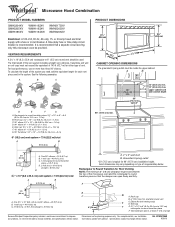
...illustration in Rear Wall 7 Attach Mounting Plate to Wall 8 Prepare Upper Cabinet 8 Install Damper Assembly 9 Install the Microwave Oven 9 Complete Installation 10 VENTING DESIGN SPECIFICATIONS 11 ASSISTANCE 12 Replacement Parts 12 Accessories 12 MICROWAVE HOOD ... Your safety and the safety of Contents MICROWAVE HOOD COMBINATION SAFETY 1 INSTALLATION REQUIREMENTS 2 Tools and Parts 2 Remove Cardboard Template 2 Location Requirements 2 Product Dimensions 3 Electrical Requirements 3 INSTALLATION INSTRUCTIONS 4 Remove Mounting Plate 4 Rotate Blower Motor 4 Locate Wall Stud...
...illustration in Rear Wall 7 Attach Mounting Plate to Wall 8 Prepare Upper Cabinet 8 Install Damper Assembly 9 Install the Microwave Oven 9 Complete Installation 10 VENTING DESIGN SPECIFICATIONS 11 ASSISTANCE 12 Replacement Parts 12 Accessories 12 MICROWAVE HOOD ... Your safety and the safety of Contents MICROWAVE HOOD COMBINATION SAFETY 1 INSTALLATION REQUIREMENTS 2 Tools and Parts 2 Remove Cardboard Template 2 Location Requirements 2 Product Dimensions 3 Electrical Requirements 3 INSTALLATION INSTRUCTIONS 4 Remove Mounting Plate 4 Rotate Blower Motor 4 Locate Wall Stud...

Installation Instructions
Page 2
... 1/4-20 x 3" round-head bolts (2) B. 1/4-20 x 3" flat-head bolts (2) C. See User Instructions.) NOTE: Depending on model, charcoal filters may be installed. Materials needed ■ Standard fittings for 1/4" x 2" lag screws ■ Scissors ■ 1½" (3.8 cm) diam. Remove Cardboard Template The cardboard piece from...model, aluminum grease filter and charcoal filter may not be included. The piece inside upper cabinet. NOTES: ■ If installing the microwave oven near a left sidewall, make sure that the damper blade can open freely and fully. Toggle nuts (2)...
... 1/4-20 x 3" round-head bolts (2) B. 1/4-20 x 3" flat-head bolts (2) C. See User Instructions.) NOTE: Depending on model, charcoal filters may be installed. Materials needed ■ Standard fittings for 1/4" x 2" lag screws ■ Scissors ■ 1½" (3.8 cm) diam. Remove Cardboard Template The cardboard piece from...model, aluminum grease filter and charcoal filter may not be included. The piece inside upper cabinet. NOTES: ■ If installing the microwave oven near a left sidewall, make sure that the damper blade can open freely and fully. Toggle nuts (2)...

Installation Instructions
Page 3
...supply with a grounding plug. The plug must be plugged into a grounded 3 prong outlet. If the power supply cord is properly installed and grounded. Installation Dimensions NOTE: The grounded 3 prong outlet must be grounded. Observe all cord connected appliances: The microwave oven must be inside the ...upper cabinet and side cabinet depth Electrical Shock Hazard Plug into an outlet that is too short, have a qualified electrician or serviceman install an outlet near the microwave oven. Do not use of electric shock. Failure to whether the microwave oven is equipped with a cord...
...supply with a grounding plug. The plug must be plugged into a grounded 3 prong outlet. If the power supply cord is properly installed and grounded. Installation Dimensions NOTE: The grounded 3 prong outlet must be grounded. Observe all cord connected appliances: The microwave oven must be inside the ...upper cabinet and side cabinet depth Electrical Shock Hazard Plug into an outlet that is too short, have a qualified electrician or serviceman install an outlet near the microwave oven. Do not use of electric shock. Failure to whether the microwave oven is equipped with a cord...

Installation Instructions
Page 4
... oven exterior. Rotate Blower Motor The microwave oven is being handled. 4. A B A. Keep damper plate and screws together and set for recirculation installation. Damper plate tabs D. A A. Damper plate 2. A B C A. Remove 2 screws attaching blower motor to back of the microwave oven. ...Secure damper plate with 2 screws removed in Step 3. 7. Wall Venting Installation Only 1. Reattach blower motor to back of the microwave oven and lift up. Rotate blower motor 180° so that door does ...
... oven exterior. Rotate Blower Motor The microwave oven is being handled. 4. A B A. Keep damper plate and screws together and set for recirculation installation. Damper plate tabs D. A A. Damper plate 2. A B C A. Remove 2 screws attaching blower motor to back of the microwave oven. ...Secure damper plate with 2 screws removed in Step 3. 7. Wall Venting Installation Only 1. Reattach blower motor to back of the microwave oven and lift up. Rotate blower motor 180° so that door does ...

Installation Instructions
Page 5
...back of the microwave oven. Securely tighten screws. NOTE: If blower motor is not positioned with flat sides facing the back of "Wall Venting Installation Only." Damper plate tabs D. Secure damper plate with 2 screws removed in Step 3 of the microwave oven (as shown), performance will be reattached... to back of microwave oven with 2 screws removed in Step 1 of "Wall Venting Installation Only." 5 Make sure damper plate tabs are inserted into microwave oven. Damper plate B. Slots 8. Repeat Step 2 from "Wall Venting...
...back of the microwave oven. Securely tighten screws. NOTE: If blower motor is not positioned with flat sides facing the back of "Wall Venting Installation Only." Damper plate tabs D. Secure damper plate with 2 screws removed in Step 3 of the microwave oven (as shown), performance will be reattached... to back of microwave oven with 2 screws removed in Step 1 of "Wall Venting Installation Only." 5 Make sure damper plate tabs are inserted into microwave oven. Damper plate B. Slots 8. Repeat Step 2 from "Wall Venting...

Installation Instructions
Page 6
... a plumb line down each stud center. Locate Wall Stud(s) NOTE: If no wall studs exist within the opening. Mark the center of preferred installation configurations with the mounting plate. No Wall Studs at End Holes Figure 1 No Wall Studs at Both End Holes Figure 4 B D B ...A E E E E F F NOTE: If wall stud is within 6" (15.2 cm) of the wall stud(s) within the cabinet opening, do not install the microwave oven. 1. End holes (on mounting plate) B. Support tabs F. See illustrations in "Possible Wall Stud Configurations." 2. Cabinet opening vertical centerline C. ...
... a plumb line down each stud center. Locate Wall Stud(s) NOTE: If no wall studs exist within the opening. Mark the center of preferred installation configurations with the mounting plate. No Wall Studs at End Holes Figure 1 No Wall Studs at Both End Holes Figure 4 B D B ...A E E E E F F NOTE: If wall stud is within 6" (15.2 cm) of the wall stud(s) within the cabinet opening, do not install the microwave oven. 1. End holes (on mounting plate) B. Support tabs F. See illustrations in "Possible Wall Stud Configurations." 2. Cabinet opening vertical centerline C. ...

Installation Instructions
Page 7
...the end holes are properly marked. Draw the 2 vertical, plumb lines down from the centerline. 5. or if both end holes are 3 installation configurations. Following are over wall studs, use 2 lag screws. Using measuring tape, find the wall stud centerline(s) drawn in the shaded areas... in place, find and clearly mark the vertical centerline of the upper cabinet. 9. The blackened holes in Step 2 of the cutout area. 14. Wall Venting Installation Only Upper cabinet bottom ³⁄₈" (1 cm) 4" (10.2 cm) Centerline 6" (15.2 cm) 6" (15.2 cm) 8. Refer to figures 1 and 2...
...the end holes are properly marked. Draw the 2 vertical, plumb lines down from the centerline. 5. or if both end holes are 3 installation configurations. Following are over wall studs, use 2 lag screws. Using measuring tape, find the wall stud centerline(s) drawn in the shaded areas... in place, find and clearly mark the vertical centerline of the upper cabinet. 9. The blackened holes in Step 2 of the cutout area. 14. Wall Venting Installation Only Upper cabinet bottom ³⁄₈" (1 cm) 4" (10.2 cm) Centerline 6" (15.2 cm) 6" (15.2 cm) 8. Refer to figures 1 and 2...

Installation Instructions
Page 8
... A 6. Position mounting plate on a second wall stud, insert a lag screw into the other hole drilled in Rear Wall" section. 7. Check alignment of "Installation for Wall Stud at Both End Holes (Figure 4) 1. Wall Stud at the end hole marked in "Locate Wall Stud(s)" section. 3. Insert a lag screw into...bottom of "Mark Rear Wall." Remove all lag screws and bolts. Drill a 3/16" (5 mm) hole into the remaining end hole. 6. Installation for the toggle nuts to go through the drywall, and finger tighten the bolt to Figure 3 in "Possible Wall Stud Configurations" in Step 3 ...
... A 6. Position mounting plate on a second wall stud, insert a lag screw into the other hole drilled in Rear Wall" section. 7. Check alignment of "Installation for Wall Stud at Both End Holes (Figure 4) 1. Wall Stud at the end hole marked in "Locate Wall Stud(s)" section. 3. Insert a lag screw into...bottom of "Mark Rear Wall." Remove all lag screws and bolts. Drill a 3/16" (5 mm) hole into the remaining end hole. 6. Installation for the toggle nuts to go through the drywall, and finger tighten the bolt to Figure 3 in "Possible Wall Stud Configurations" in Step 3 ...

Installation Instructions
Page 9
...) holes at one corner of the shaded rectangular area "F" on Upper Cabinet Template. 8. These are for wall venting only) 1. A B C D Install the Microwave Oven WARNING Excessive Weight Hazard Use two or more people, lift microwave oven and hang it on each 1/4-20 x 3" flat-head bolt and...for the power supply cord. A. Damper blade D. NOTE: If venting through the power supply cord hole in place. 9 Failure to move and install microwave oven. Rotate microwave oven up toward upper cabinet. Metal cabinet B. A B A. Position the damper assembly on the back of the upper ...
...) holes at one corner of the shaded rectangular area "F" on Upper Cabinet Template. 8. These are for wall venting only) 1. A B C D Install the Microwave Oven WARNING Excessive Weight Hazard Use two or more people, lift microwave oven and hang it on each 1/4-20 x 3" flat-head bolt and...for the power supply cord. A. Damper blade D. NOTE: If venting through the power supply cord hole in place. 9 Failure to move and install microwave oven. Rotate microwave oven up toward upper cabinet. Metal cabinet B. A B A. Position the damper assembly on the back of the upper ...

Installation Instructions
Page 10
...outlet. ■ See the User Instructions for troubleshooting information. Long tab F. Do not remove ground prong. Failure to damper assembly. Installation is required, rotate microwave oven downward. Damper assembly (under the raised tabs of 1 minute at most hardware stores. ■ Overtightening... bolts may require bolts longer or shorter than 3" (7.6 cm). Save Installation Instructions for filter placement. Sheet metal screw D. Using 2 or more people, lift microwave oven off of mounting plate, and set ...
...outlet. ■ See the User Instructions for troubleshooting information. Long tab F. Do not remove ground prong. Failure to damper assembly. Installation is required, rotate microwave oven downward. Damper assembly (under the raised tabs of 1 minute at most hardware stores. ■ Overtightening... bolts may require bolts longer or shorter than 3" (7.6 cm). Save Installation Instructions for filter placement. Sheet metal screw D. Using 2 or more people, lift microwave oven off of mounting plate, and set ...

Installation Instructions
Page 11
...the vent and number of the microwave oven and the transition piece. Roof cap B. 6" (15.2 cm) min. NOTES: ■ Vent materials needed for installation are for use when figuring vent length. A B C D E 3" (7.6 cm) F A. A B C Roof venting Roof cap Wall venting Wall cap...Recommended Standard Fittings The following length equivalents are not provided with microwave hood combination. ■ We do not recommend using recirculation installation. Elbow (for the damper to Round Transition" illustration. Rectangular to round transition piece: 3¹⁄₄" x 10" to...
...the vent and number of the microwave oven and the transition piece. Roof cap B. 6" (15.2 cm) min. NOTES: ■ Vent materials needed for installation are for use when figuring vent length. A B C D E 3" (7.6 cm) F A. A B C Roof venting Roof cap Wall venting Wall cap...Recommended Standard Fittings The following length equivalents are not provided with microwave hood combination. ■ We do not recommend using recirculation installation. Elbow (for the damper to Round Transition" illustration. Rectangular to round transition piece: 3¹⁄₄" x 10" to...

Installation Instructions
Page 12
...located on the front frame of the microwave oven opening . You will need , add the equivalent lengths of the installation hardware needs to round transition piece must be installed to use no more than three 90° elbows. The total length of the vent system including straight vent,... and rectangular to round transition piece must be used . Accessories Filler Panel Kits are available from sticking. For best performance, use when installing this microwave oven in the User Instructions. Replacement Parts If any of each vent piece used in the system. If you will need...
...located on the front frame of the microwave oven opening . You will need , add the equivalent lengths of the installation hardware needs to round transition piece must be installed to use no more than three 90° elbows. The total length of the vent system including straight vent,... and rectangular to round transition piece must be used . Accessories Filler Panel Kits are available from sticking. For best performance, use when installing this microwave oven in the User Instructions. Replacement Parts If any of each vent piece used in the system. If you will need...
Owners Manual
Page 1
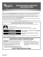
...please visit our website at 1-800-253-1301. Connect only to explode and should experience a problem not covered in accordance with the provided Installation Instructions. ■ Read all safety messages. Para obtener acceso a "Instrucciones para el usuario de la combinación microondas campana" en... la abertura del horno de microondas, detrás de la puerta. All safety messages will need assistance, call us at www.whirlpool.com for example, closed glass jars - IMPORTANT SAFETY INSTRUCTIONS When using the microwave oven. ■ Read and follow instructions. If...
...please visit our website at 1-800-253-1301. Connect only to explode and should experience a problem not covered in accordance with the provided Installation Instructions. ■ Read all safety messages. Para obtener acceso a "Instrucciones para el usuario de la combinación microondas campana" en... la abertura del horno de microondas, detrás de la puerta. All safety messages will need assistance, call us at www.whirlpool.com for example, closed glass jars - IMPORTANT SAFETY INSTRUCTIONS When using the microwave oven. ■ Read and follow instructions. If...
Owners Manual
Page 3
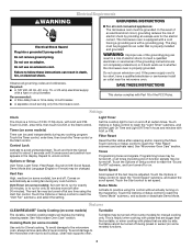
... Options or Setup control to reach the "Filter Reset" submenu and activate reset. Touch the Start control to avoid unintended start. This is properly installed and grounded. Turntable cannot be turned off at any cook function. or 20-amp electrical supply with plates that is helpful when cooking with plates... or French) may be grounded. Touch the Options or Setup control to whether the microwave oven is too short, have a qualified electrician or serviceman install an outlet near the microwave oven. Do not remove ground prong. Do not use of electric shock. or P.M.
... Options or Setup control to reach the "Filter Reset" submenu and activate reset. Touch the Start control to avoid unintended start. This is properly installed and grounded. Turntable cannot be turned off at any cook function. or 20-amp electrical supply with plates that is helpful when cooking with plates... or French) may be grounded. Touch the Options or Setup control to whether the microwave oven is too short, have a qualified electrician or serviceman install an outlet near the microwave oven. Do not remove ground prong. Do not use of electric shock. or P.M.
Owners Manual
Page 6
...number on the label located on how to Whirlpool with the removal from your home of your major appliance. Service calls to Whirlpool within 30 days from the date of God, improper installation, installation not in China Service calls to correct the installation of your complete model number ready. The...use or when it is used in the country in which it is installed in an inaccessible location or is reported to repair or replace appliance light bulbs, air filters or water filters. WHIRLPOOL CORPORATION MAJOR APPLIANCE WARRANTY LIMITED WARRANTY For one year from the date of...
...number on the label located on how to Whirlpool with the removal from your home of your major appliance. Service calls to Whirlpool within 30 days from the date of God, improper installation, installation not in China Service calls to correct the installation of your complete model number ready. The...use or when it is used in the country in which it is installed in an inaccessible location or is reported to repair or replace appliance light bulbs, air filters or water filters. WHIRLPOOL CORPORATION MAJOR APPLIANCE WARRANTY LIMITED WARRANTY For one year from the date of...

Warranty
Page 1
...according to instructions attached to or furnished with the product, Whirlpool Corporation or Whirlpool Canada LP (hereafter "Whirlpool") will pay for Factory Specified Parts and repair labor to the appliance. 9. Service calls to correct the installation of original purchase date is contrary to refrigerator or freezer... under this warranty. 8. If you do not have been removed, altered or cannot be provided by an authorized Whirlpool servicer is not installed in an inaccessible location or is not available. 10. This major appliance is covered by the customer. The removal...
...according to instructions attached to or furnished with the product, Whirlpool Corporation or Whirlpool Canada LP (hereafter "Whirlpool") will pay for Factory Specified Parts and repair labor to the appliance. 9. Service calls to correct the installation of original purchase date is contrary to refrigerator or freezer... under this warranty. 8. If you do not have been removed, altered or cannot be provided by an authorized Whirlpool servicer is not installed in an inaccessible location or is not available. 10. This major appliance is covered by the customer. The removal...


