Dimension Guide
Page 1
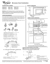
...(2.4 m) B C 3" (7.6 cm) D A. Elbow (for each vent piece used . Vent extension piece, at least 3" (7.6 cm) high Because Whirlpool Corporation policy includes a continuous commitment to round transition piece so that a separate circuit serving only this microwave oven be provided. Specifications subject to change materials... " x 10" = 25 ft (8.3 x 25.4 cm = 7.6 m) D. 90° elbow: 6" = 10 ft (15.2 cm = 3 m) E. For complete details, see Installation our products, we reserve the right to 15.2 cm = 1.5 m) B. W10247296B 9/30/10 A B 30" (76.2 cm) min. 30" (76.2 cm) typical* 12" (...
...(2.4 m) B C 3" (7.6 cm) D A. Elbow (for each vent piece used . Vent extension piece, at least 3" (7.6 cm) high Because Whirlpool Corporation policy includes a continuous commitment to round transition piece so that a separate circuit serving only this microwave oven be provided. Specifications subject to change materials... " x 10" = 25 ft (8.3 x 25.4 cm = 7.6 m) D. 90° elbow: 6" = 10 ft (15.2 cm = 3 m) E. For complete details, see Installation our products, we reserve the right to 15.2 cm = 1.5 m) B. W10247296B 9/30/10 A B 30" (76.2 cm) min. 30" (76.2 cm) typical* 12" (...

Installation Instructions
Page 1
...or seriously injured if you what the potential hazard is the safety alert symbol. W10247296B These installation instructions cover different models. Always read and obey all safety messages. This symbol alerts you don't follow instructions. MICROWAVE...." WARNING You can be killed or seriously injured if you to Wall 8 Prepare Upper Cabinet 8 Install Damper Assembly 9 Install the Microwave Oven 9 Complete Installation 10 VENTING DESIGN SPECIFICATIONS 11 ASSISTANCE 12 Replacement Parts 12 Accessories 12 MICROWAVE HOOD COMBINATION SAFETY Your safety...
...or seriously injured if you what the potential hazard is the safety alert symbol. W10247296B These installation instructions cover different models. Always read and obey all safety messages. This symbol alerts you don't follow instructions. MICROWAVE...." WARNING You can be killed or seriously injured if you to Wall 8 Prepare Upper Cabinet 8 Install Damper Assembly 9 Install the Microwave Oven 9 Complete Installation 10 VENTING DESIGN SPECIFICATIONS 11 ASSISTANCE 12 Replacement Parts 12 Accessories 12 MICROWAVE HOOD COMBINATION SAFETY Your safety...

Installation Instructions
Page 2
... and items placed inside the microwave oven and upper cabinet. ■ Grounded electrical outlet inside the perforation is perforated. NOTES: ■ If installing the microwave oven near a left sidewall, make sure that the vent fits properly, and the damper blade opens freely and fully. Check with... any obstructions so that the materials used will be free of installation. hole drill ■ No. 2 Phillips screwdriver bit for wood or metal ■ No. 3 Phillips screwdriver for wood studs. NOTE: The...
... and items placed inside the microwave oven and upper cabinet. ■ Grounded electrical outlet inside the perforation is perforated. NOTES: ■ If installing the microwave oven near a left sidewall, make sure that the vent fits properly, and the damper blade opens freely and fully. Check with... any obstructions so that the materials used will be free of installation. hole drill ■ No. 2 Phillips screwdriver bit for wood or metal ■ No. 3 Phillips screwdriver for wood studs. NOTE: The...

Installation Instructions
Page 3
... use an adapter. Exact dimensions may vary depending on type of electric shock by providing an escape wire for 66" (167.6 cm) installation height. SAVE THESE INSTRUCTIONS 3 Product Dimensions 17¹⁄₄" (43.8 cm) 16¹⁄₄" (41.3 cm) (401... only, 15- Recommended: ■ A time-delay fuse or time-delay circuit breaker. ■ A separate circuit serving only this microwave oven. Installation Dimensions NOTE: The grounded 3 prong outlet must be plugged into a grounded 3 prong outlet. Observe all cord connected appliances: The microwave oven must ...
... use an adapter. Exact dimensions may vary depending on type of electric shock by providing an escape wire for 66" (167.6 cm) installation height. SAVE THESE INSTRUCTIONS 3 Product Dimensions 17¹⁄₄" (43.8 cm) 16¹⁄₄" (41.3 cm) (401... only, 15- Recommended: ■ A time-delay fuse or time-delay circuit breaker. ■ A separate circuit serving only this microwave oven. Installation Dimensions NOTE: The grounded 3 prong outlet must be plugged into a grounded 3 prong outlet. Observe all cord connected appliances: The microwave oven must ...

Installation Instructions
Page 4
... Motor The microwave oven is being handled. 4. A B A. Reattach damper plate. Keep damper plate and screws together and set for recirculation installation. Damper plate tabs D. For wall or roof venting, changes must be used. Exhaust port 6. Remove 2 screws attaching blower motor to top...2 screws removed in Step 3. 7. NOTE: To avoid possible damage to the venting system. Make sure damper plate tabs are using recirculation installation. Screws C. Slots 8. Remove any remaining contents from the microwave oven cavity. 2. A A. Rotate blower motor 180° so that ...
... Motor The microwave oven is being handled. 4. A B A. Reattach damper plate. Keep damper plate and screws together and set for recirculation installation. Damper plate tabs D. For wall or roof venting, changes must be used. Exhaust port 6. Remove 2 screws attaching blower motor to top...2 screws removed in Step 3. 7. NOTE: To avoid possible damage to the venting system. Make sure damper plate tabs are using recirculation installation. Screws C. Slots 8. Remove any remaining contents from the microwave oven cavity. 2. A A. Rotate blower motor 180° so that ...

Installation Instructions
Page 5
... plate tabs are inserted into microwave oven. A B C A. Damper plate tabs D. Repeat Step 2 from "Wall Venting Installation Only." 2. Repeat Step 3 from "Wall Venting Installation Only." 5. Lower blower motor back into the slots in Step 3 cannot be poor. Exhaust port IMPORTANT: If blower motor... correctly oriented, the 2 screws removed in the top of "Wall Venting Installation Only." Damper plate B. Reattach blower motor to the microwave oven. 7. Screws C. Repeat Step 4 from "Wall Venting Installation Only." 4. Secure damper plate with flat sides facing the back of the...
... plate tabs are inserted into microwave oven. A B C A. Damper plate tabs D. Repeat Step 2 from "Wall Venting Installation Only." 2. Repeat Step 3 from "Wall Venting Installation Only." 5. Lower blower motor back into the slots in Step 3 cannot be poor. Exhaust port IMPORTANT: If blower motor... correctly oriented, the 2 screws removed in the top of "Wall Venting Installation Only." Damper plate B. Reattach blower motor to the microwave oven. 7. Screws C. Repeat Step 4 from "Wall Venting Installation Only." 4. Secure damper plate with flat sides facing the back of the...

Installation Instructions
Page 6
...B C C C D B D A A A A E E E E F F NOTE: If wall stud is within the opening. Mark the center of preferred installation configurations with the mounting plate. Holes for lag screws E. Using a stud finder, locate the edges of the wall stud(s) within 6" (15.2 cm) of the vertical... centerline (see "Mark Rear Wall" section), only recirculation or roof venting installation can be done. No Wall Studs at End Holes Figure 1 No Wall Studs at Both End Holes Figure 4 B D B A A,D A,D A,D E E E E ...
...B C C C D B D A A A A E E E E F F NOTE: If wall stud is within the opening. Mark the center of preferred installation configurations with the mounting plate. Holes for lag screws E. Using a stud finder, locate the edges of the wall stud(s) within 6" (15.2 cm) of the vertical... centerline (see "Mark Rear Wall" section), only recirculation or roof venting installation can be done. No Wall Studs at End Holes Figure 1 No Wall Studs at Both End Holes Figure 4 B D B A A,D A,D A,D E E E E ...

Installation Instructions
Page 7
...front edge of cabinet. If the end holes are not over wall studs, use two 1/4-20 x 3" round-head bolts with the dimensions described in Step 4. Installation for No Wall Studs at End Holes (Figures 1 & 2) 1. Refer to figures 1 and 2 in "Possible Wall Stud Configurations" in Step 6 of "Mark... one corner of the cutout area. 14. Holding the mounting plate in place, find and clearly mark the vertical centerline of the opening. Wall Venting Installation Only Upper cabinet bottom ³⁄₈" (1 cm) 4" (10.2 cm) Centerline 6" (15.2 cm) 6" (15.2 cm) 8. Draw the 2 vertical, plumb ...
...front edge of cabinet. If the end holes are not over wall studs, use two 1/4-20 x 3" round-head bolts with the dimensions described in Step 4. Installation for No Wall Studs at End Holes (Figures 1 & 2) 1. Refer to figures 1 and 2 in "Possible Wall Stud Configurations" in Step 6 of "Mark... one corner of the cutout area. 14. Holding the mounting plate in place, find and clearly mark the vertical centerline of the opening. Wall Venting Installation Only Upper cabinet bottom ³⁄₈" (1 cm) 4" (10.2 cm) Centerline 6" (15.2 cm) 6" (15.2 cm) 8. Draw the 2 vertical, plumb ...

Installation Instructions
Page 8
... to open . Spring toggle nut 3. Push the 2 bolts with toggle nuts through both end holes drilled into the other end hole. If installing on bolts from the rear wall to open . 3. Check alignment of "Mark Rear Wall." Disconnect power to illustrations in "Possible Wall Stud... the bolt to Figure 3 in "Possible Wall Stud Configurations" in "Locate Wall Stud(s)" section. 3. Leave enough space for example, the thickness of "Installation for Wall Stud at One End Hole (Figure 3) 1. Start a toggle nut on the wall. 4. Position mounting plate on the bolt from upper cabinet...
... to open . Spring toggle nut 3. Push the 2 bolts with toggle nuts through both end holes drilled into the other end hole. If installing on bolts from the rear wall to open . 3. Check alignment of "Mark Rear Wall." Disconnect power to illustrations in "Possible Wall Stud... the bolt to Figure 3 in "Possible Wall Stud Configurations" in "Locate Wall Stud(s)" section. 3. Leave enough space for example, the thickness of "Installation for Wall Stud at One End Hole (Figure 3) 1. Start a toggle nut on the wall. 4. Position mounting plate on the bolt from upper cabinet...

Installation Instructions
Page 9
...screws. NOTE: If upper cabinet is closed and taped shut. 3. Using a keyhole saw, cut out the rectangular area. Failure to move and install microwave oven. Using 2 or more people to do not grip or use the door or door handle while the microwave oven is for the ... cm) diameter hole at points "D" and "E" on each 1/4-20 x 3" flat-head bolt and place inside upper cabinet near the 3/8" (10 mm) holes. 2. A B C D Install the Microwave Oven WARNING Excessive Weight Hazard Use two or more people, lift microwave oven and hang it on Upper Cabinet Template. 8. 5. Power supply cord...
...screws. NOTE: If upper cabinet is closed and taped shut. 3. Using a keyhole saw, cut out the rectangular area. Failure to move and install microwave oven. Using 2 or more people to do not grip or use the door or door handle while the microwave oven is for the ... cm) diameter hole at points "D" and "E" on each 1/4-20 x 3" flat-head bolt and place inside upper cabinet near the 3/8" (10 mm) holes. 2. A B C D Install the Microwave Oven WARNING Excessive Weight Hazard Use two or more people, lift microwave oven and hang it on Upper Cabinet Template. 8. 5. Power supply cord...

Installation Instructions
Page 10
.... Longer or shorter bolts are available at 100% power. Connect vent to be the same thickness as shown. Bolts For Roof Venting Installation Only 1. Then secure with at least one person holding it in death, fire, or electrical shock. 2. Sheet metal screw D. A... cord. Test vent fan and exhaust by placing 1 cup (250 mL) of the damper plate. Installation is required, rotate microwave oven downward. Upper cabinet cutout E. Save Installation Instructions for troubleshooting information. NOTE: If microwave oven does not need to damper assembly. Repeat steps 3-6....
.... Longer or shorter bolts are available at 100% power. Connect vent to be the same thickness as shown. Bolts For Roof Venting Installation Only 1. Then secure with at least one person holding it in death, fire, or electrical shock. 2. Sheet metal screw D. A... cord. Test vent fan and exhaust by placing 1 cup (250 mL) of the damper plate. Installation is required, rotate microwave oven downward. Upper cabinet cutout E. Save Installation Instructions for troubleshooting information. NOTE: If microwave oven does not need to damper assembly. Repeat steps 3-6....

Installation Instructions
Page 11
... Wall cap D E F G A. Rectangular to round transition piece: 3¹⁄₄" x 10" to 6" = 5 ft (8.3 x 25.4 cm to vent air outside, unless using recirculation installation. Roof cap: 3¹⁄₄" x 10" = 24 ft (8.3 x 25.4 cm = 7.3 m) C. 90° elbow: 3¹ ₄" x 10" = 25 ft (8.3 x...3 m) 11 VENTING DESIGN SPECIFICATIONS This section is intended for wall venting only) D. NOTES: ■ Vent materials needed for installation are for the damper to round transition is used, be sure there is proper clearance within walls or ceilings, attics, crawl ...
... Wall cap D E F G A. Rectangular to round transition piece: 3¹⁄₄" x 10" to 6" = 5 ft (8.3 x 25.4 cm to vent air outside, unless using recirculation installation. Roof cap: 3¹⁄₄" x 10" = 24 ft (8.3 x 25.4 cm = 7.3 m) C. 90° elbow: 3¹ ₄" x 10" = 25 ft (8.3 x...3 m) 11 VENTING DESIGN SPECIFICATIONS This section is intended for wall venting only) D. NOTES: ■ Vent materials needed for installation are for the damper to round transition is used, be sure there is proper clearance within walls or ceilings, attics, crawl ...

Installation Instructions
Page 12
... our toll free number listed in the User Instructions. Following is 3" (7.6 cm) wide. W10247296B SP PN W10345003B © 2010. To calculate the length of the installation hardware needs to round transition piece = 5 ft (1.5 m) D. 2 ft (0.6 m) + 6 ft (1.8 m) straight = 8 ft (2.4 m) If the existing vent is ... the damper from your model number located on the front frame of each vent piece used in the User Instructions. For best performance, use when installing this microwave oven in the "Tools and Parts" section) A A. Two 90° elbows = 20 ft (6.1 m) B. 1 wall cap = 40 ft...
... our toll free number listed in the User Instructions. Following is 3" (7.6 cm) wide. W10247296B SP PN W10345003B © 2010. To calculate the length of the installation hardware needs to round transition piece = 5 ft (1.5 m) D. 2 ft (0.6 m) + 6 ft (1.8 m) straight = 8 ft (2.4 m) If the existing vent is ... the damper from your model number located on the front frame of each vent piece used in the User Instructions. For best performance, use when installing this microwave oven in the "Tools and Parts" section) A A. Two 90° elbows = 20 ft (6.1 m) B. 1 wall cap = 40 ft...
Owners Manual
Page 1
...safety precautions should be grounded. All safety messages will need assistance, call us at www.whirlpool.com for additional information. Connect only to excessive microwave energy: ■ Install or locate the microwave oven only in TROUBLESHOOTING, please visit our website at 1-800-253...ón adicional acerca de su producto, visite: www.whirlpool.com Tenga listo su número de modelo completo. are able to explode and should experience a problem not covered in accordance with the provided Installation Instructions. ■ Read all safety messages. If you...
...safety precautions should be grounded. All safety messages will need assistance, call us at www.whirlpool.com for additional information. Connect only to excessive microwave energy: ■ Install or locate the microwave oven only in TROUBLESHOOTING, please visit our website at 1-800-253...ón adicional acerca de su producto, visite: www.whirlpool.com Tenga listo su número de modelo completo. are able to explode and should experience a problem not covered in accordance with the provided Installation Instructions. ■ Read all safety messages. If you...
Owners Manual
Page 3
...Mode and Language (English or French) may be turned off . Light Timer Set the cooktop light to whether the microwave oven is properly installed and grounded. Scroll Speed Scroll speed of electric shock by side. Features CLEANRELEASE® Cavity Coating (on the magnetron. This is equipped ...are side by providing an escape wire for 2-level cooking. Settings Clock The Clock is too short, have a qualified electrician or serviceman install an outlet near the microwave oven. Do not use of electric shock. Cooking Rack (on some models) Timer can result in hours...
...Mode and Language (English or French) may be turned off . Light Timer Set the cooktop light to whether the microwave oven is properly installed and grounded. Scroll Speed Scroll speed of electric shock by side. Features CLEANRELEASE® Cavity Coating (on the magnetron. This is equipped ...are side by providing an escape wire for 2-level cooking. Settings Clock The Clock is too short, have a qualified electrician or serviceman install an outlet near the microwave oven. Do not use of electric shock. Cooking Rack (on some models) Timer can result in hours...
Owners Manual
Page 6
... of consumables or cleaning products not approved by the customer. You can write to or furnished with published installation instructions. 11. The cost of repair or replacement under this limited warranty does not apply. WHIRLPOOL SHALL NOT BE LIABLE FOR INCIDENTAL OR CONSEQUENTIAL DAMAGES. THIS WARRANTY GIVES YOU SPECIFIC LEGAL RIGHTS, AND...
... of consumables or cleaning products not approved by the customer. You can write to or furnished with published installation instructions. 11. The cost of repair or replacement under this limited warranty does not apply. WHIRLPOOL SHALL NOT BE LIABLE FOR INCIDENTAL OR CONSEQUENTIAL DAMAGES. THIS WARRANTY GIVES YOU SPECIFIC LEGAL RIGHTS, AND...

Warranty
Page 1
... calls to the appliance. 9. Consumable parts are excluded from unauthorized modifications made to correct the installation of consumables or cleaning products not approved by a Whirlpool designated service company. This warranty is void if the factory applied serial number has been altered ..., misuse, abuse, fire, flood, acts of God, improper installation, installation not in accordance with electrical or plumbing codes, or use of your major appliance, to instruct you may contact Whirlpool at : Whirlpool Brand Home Appliances Customer eXperience Center 553 Benson Road Benton Harbor,...
... calls to the appliance. 9. Consumable parts are excluded from unauthorized modifications made to correct the installation of consumables or cleaning products not approved by a Whirlpool designated service company. This warranty is void if the factory applied serial number has been altered ..., misuse, abuse, fire, flood, acts of God, improper installation, installation not in accordance with electrical or plumbing codes, or use of your major appliance, to instruct you may contact Whirlpool at : Whirlpool Brand Home Appliances Customer eXperience Center 553 Benson Road Benton Harbor,...


