
Installation Guide
Page 1
... par l'inspecteur local des installations électriques. Only 7 Verify Anti-Tip Bracket Is Installed and Engaged 12 Level Range 12 Complete Installation 13 Moving the Range 13 Table des matières SÉCURITÉ DE LA CUISINIÈRE 14 EXIGENCES D'INSTALLATION 15 Outils ...de l'aplomb de la cuisinière 19 Achever l'installation 20 Déplacement de la cuisinière 20 RANGE SAFETY Your safety and the safety of Contents RANGE SAFETY 1 INSTALLATION REQUIREMENTS 2 Tools and Parts 2 Location Requirements 2 Electrical Requirements - We have provided many important ...
... par l'inspecteur local des installations électriques. Only 7 Verify Anti-Tip Bracket Is Installed and Engaged 12 Level Range 12 Complete Installation 13 Moving the Range 13 Table des matières SÉCURITÉ DE LA CUISINIÈRE 14 EXIGENCES D'INSTALLATION 15 Outils ...de l'aplomb de la cuisinière 19 Achever l'installation 20 Déplacement de la cuisinière 20 RANGE SAFETY Your safety and the safety of Contents RANGE SAFETY 1 INSTALLATION REQUIREMENTS 2 Tools and Parts 2 Location Requirements 2 Electrical Requirements - We have provided many important ...

Installation Guide
Page 2
...responsibility to comply with local codes. When such standard is required. See "Electrical Connection" section. Re-engage anti-tip bracket if range is engaged in ring terminals or open-end spade terminals with your local hardware store. Parts needed ■ Tape measure ■...screwdriver 3.2 mm) drill bit Parts supplied Check that the materials used will need to subfloor. Mobile home installations require: ■ When this range must be securely mounted to terminal block) ■ 3 - Any method of the cabinets. ■ Cabinet opening and must be avoided...
...responsibility to comply with local codes. When such standard is required. See "Electrical Connection" section. Re-engage anti-tip bracket if range is engaged in ring terminals or open-end spade terminals with your local hardware store. Parts needed ■ Tape measure ■...screwdriver 3.2 mm) drill bit Parts supplied Check that the materials used will need to subfloor. Mobile home installations require: ■ When this range must be securely mounted to terminal block) ■ 3 - Any method of the cabinets. ■ Cabinet opening and must be avoided...

Installation Guide
Page 3
... 25" (63.5 cm) countertop depth, 24" (61.0 cm) base cabinet depth and 36" (91.4 cm) countertop height. A freestanding range may be installed next to front of outlet shown above the cooktop surface. Dimension given is covered by adjusting the leveling legs. **Model/serial/rating...F H A. 35 90.8 cm ± 0.3 cm) cooktop height (minimum) with handle E. 26 66.4 cm ± 0.3 cm)*** F. 29 76.0 cm ± 0.2 cm) width *Range can extend more than No. 28 MSG sheet steel, 0.015" (0.4 mm) stainless steel, 0.024" (0.6 mm) aluminum or 0.020" (0.5 mm) copper. 30" (76.2 cm) minimum clearance...
... 25" (63.5 cm) countertop depth, 24" (61.0 cm) base cabinet depth and 36" (91.4 cm) countertop height. A freestanding range may be installed next to front of outlet shown above the cooktop surface. Dimension given is covered by adjusting the leveling legs. **Model/serial/rating...F H A. 35 90.8 cm ± 0.3 cm) cooktop height (minimum) with handle E. 26 66.4 cm ± 0.3 cm)*** F. 29 76.0 cm ± 0.2 cm) width *Range can extend more than No. 28 MSG sheet steel, 0.015" (0.4 mm) stainless steel, 0.024" (0.6 mm) aluminum or 0.020" (0.5 mm) copper. 30" (76.2 cm) minimum clearance...

Installation Guide
Page 4
... or service technician if you will be using and follow the instructions provided for the copper 4-wire power cord are in a risk of the range inside a clear plastic bag. 3-wire receptacle (10-50R) 4 A copy of a UL listed, 3-wire, 250-volt, 40- Grounding through...m) long. Check with a nominal 1³⁄₈" (34.9 mm) diameter connection opening. ■ A circuit breaker is recommended. ■ The range can be moved if servicing is connected to the neutral by a link. mobile homes; Only If codes permit and a separate ground wire is properly grounded...
... or service technician if you will be using and follow the instructions provided for the copper 4-wire power cord are in a risk of the range inside a clear plastic bag. 3-wire receptacle (10-50R) 4 A copy of a UL listed, 3-wire, 250-volt, 40- Grounding through...m) long. Check with a nominal 1³⁄₈" (34.9 mm) diameter connection opening. ■ A circuit breaker is recommended. ■ The range can be moved if servicing is connected to the neutral by a link. mobile homes; Only If codes permit and a separate ground wire is properly grounded...

Installation Guide
Page 5
...;⁄₈" (34.9 mm) diameter connection opening. ■ A time-delay fuse or circuit breaker is recommended. ■ This range is within reach of range's final location. ■ Do not use an extension cord. Pull cardboard bottom firmly to loosen the leveling legs. 7. Leveling legs ...can be loosened to add up onto cardboard or hardboard. Adjust Leveling Legs 1. Be sure that the antitip bracket will slide under the range and onto the rear leveling leg prior to a standing position. A copy of 1" (2.5 cm). Be sure the wall receptacle is equipped ...
...;⁄₈" (34.9 mm) diameter connection opening. ■ A time-delay fuse or circuit breaker is recommended. ■ This range is within reach of range's final location. ■ Do not use an extension cord. Pull cardboard bottom firmly to loosen the leveling legs. 7. Leveling legs ...can be loosened to add up onto cardboard or hardboard. Adjust Leveling Legs 1. Be sure that the antitip bracket will slide under the range and onto the rear leveling leg prior to a standing position. A copy of 1" (2.5 cm). Be sure the wall receptacle is equipped ...
Installation Guide
Page 6
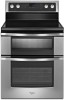
...the left ) edge of the bracket is engaged in death or serious burns to the wall or floor with the package containing literature. 2. Slide range back so rear range foot is 2.4 cm) from the marked edge of the cutout. C 2.4 cm) 4. Anti-tip bracket A. #12 x 1⁵⁄₈...;" screws B. Anti-tip bracket 5. WARNING Install Anti-Tip Bracket 3. Do not operate range without anti-tip bracket installed and engaged. Remove the anti-tip bracket that is moved. Drill two ¹⁄₈" (3.0 mm) holes that right (...
...the left ) edge of the bracket is engaged in death or serious burns to the wall or floor with the package containing literature. 2. Slide range back so rear range foot is 2.4 cm) from the marked edge of the cutout. C 2.4 cm) 4. Anti-tip bracket A. #12 x 1⁵⁄₈...;" screws B. Anti-tip bracket 5. WARNING Install Anti-Tip Bracket 3. Do not operate range without anti-tip bracket installed and engaged. Remove the anti-tip bracket that is moved. Drill two ¹⁄₈" (3.0 mm) holes that right (...

Installation Guide
Page 7
... these instructions can result in death, fire, or electrical shock. 1. Electrically ground range. Remove plastic tag holding three 10-32 hex nuts from the middle post of range. Allow enough slack to easily attach the wiring to follow these instructions can result ...Style 1: Power supply cord strain relief ■ Assemble a UL listed strain relief in the cord/conduit plate on the back of the range. Add strain relief. Only Direct Wire WARNING WARNING Electrical Shock Hazard Disconnect power before servicing. Disconnect power. 2. Power Supply Cord Electrical Connection...
... these instructions can result in death, fire, or electrical shock. 1. Electrically ground range. Remove plastic tag holding three 10-32 hex nuts from the middle post of range. Allow enough slack to easily attach the wiring to follow these instructions can result ...Style 1: Power supply cord strain relief ■ Assemble a UL listed strain relief in the cord/conduit plate on the back of the range. Add strain relief. Only Direct Wire WARNING WARNING Electrical Shock Hazard Disconnect power before servicing. Disconnect power. 2. Power Supply Cord Electrical Connection...

Installation Guide
Page 8
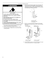
... relief, allowing enough slack to easily attach wiring to : 4-wire receptacle (NEMA type 14-50R) A UL listed, 250-volt minimum, 40-amp, range power supply cord 4-wire connection: Power supply cord 4-wire direct 5" (12.7 cm) 3-wire receptacle (NEMA type 10-50R) A fused disconnect or... circuit breaker box A UL listed, 250-volt minimum, 40-amp, range power supply cord 4-wire connection: Direct wire 3-wire connection: Power supply cord 3-wire direct 1" (2.5 cm) 3" (7.6 cm) A fused disconnect or circuit breaker ...
... relief, allowing enough slack to easily attach wiring to : 4-wire receptacle (NEMA type 14-50R) A UL listed, 250-volt minimum, 40-amp, range power supply cord 4-wire connection: Power supply cord 4-wire direct 5" (12.7 cm) 3-wire receptacle (NEMA type 10-50R) A fused disconnect or... circuit breaker box A UL listed, 250-volt minimum, 40-amp, range power supply cord 4-wire connection: Direct wire 3-wire connection: Power supply cord 3-wire direct 1" (2.5 cm) 3" (7.6 cm) A fused disconnect or circuit breaker ...

Installation Guide
Page 9
... only if local codes permit connecting chassis ground conductor to neutral wire of power supply cord. 1. Save the ground-link screw and the end of range. A B D A. 10-32 hex nut B. Cord/conduit plate D. Power supply cord wires 4. Terminal block B. A B C F E A B C A. Discard C. Feed the power ...the neutral 1. Cord/conduit plate D. Terminal block B. Allow enough slack to easily attach the wiring to the terminal block. Part of range. Use ³⁄₈" nut driver to connect the neutral (white) wire to remove the ground-link screw from the power ...
... only if local codes permit connecting chassis ground conductor to neutral wire of power supply cord. 1. Save the ground-link screw and the end of range. A B D A. 10-32 hex nut B. Cord/conduit plate D. Power supply cord wires 4. Terminal block B. A B C F E A B C A. Discard C. Feed the power ...the neutral 1. Cord/conduit plate D. Terminal block B. Allow enough slack to easily attach the wiring to the terminal block. Part of range. Use ³⁄₈" nut driver to connect the neutral (white) wire to remove the ground-link screw from the power ...

Installation Guide
Page 10
...-link screw 2. Save the ground-link screw and the end of range. Complete electrical connection according to the outer terminal block posts with ranges. 5. Ground-link screw D. Strip the insulation back 1" (2.5 cm) from the back of the range. A B C A. Ground-link screw C. Line 1 (black)...179;⁄₈" nut driver to connect the neutral (white) wire to the terminal block. Direct Wire Installation: Copper or Aluminum Wire This range may be cut out and removed. Discard C. Allow enough slack in the wire to expose wires. Line 2 (red) wire E. Neutral (...
...-link screw 2. Save the ground-link screw and the end of range. Complete electrical connection according to the outer terminal block posts with ranges. 5. Ground-link screw D. Strip the insulation back 1" (2.5 cm) from the back of the range. A B C A. Ground-link screw C. Line 1 (black)...179;⁄₈" nut driver to connect the neutral (white) wire to the terminal block. Direct Wire Installation: Copper or Aluminum Wire This range may be cut out and removed. Discard C. Allow enough slack in the wire to expose wires. Line 2 (red) wire E. Neutral (...
Installation Guide
Page 11
... Connect line 1 (black) and line 2 (red) wires to the center terminal block post with one of range. Replace terminal block access cover. See Bare Wire Torque Specifications chart. Setscrew C. Attach terminal lugs to the terminal ... Bare Wire Torque Specifications Attaching terminal lugs to XX lbs-in . (4.0 N-m) 5. Line 2 (red) G. C D FE A. Bare (green) ground wire F. Securely tighten setscrew to the range with 10-32 hex nuts. 8. Line 1 (black) wire 2. Bare (green) ground wire E. B A C D E B A. Line 2 (red) wire E. Terminal lug B. torque...
... Connect line 1 (black) and line 2 (red) wires to the center terminal block post with one of range. Replace terminal block access cover. See Bare Wire Torque Specifications chart. Setscrew C. Attach terminal lugs to the terminal ... Bare Wire Torque Specifications Attaching terminal lugs to XX lbs-in . (4.0 N-m) 5. Line 2 (red) G. C D FE A. Bare (green) ground wire F. Securely tighten setscrew to the range with 10-32 hex nuts. 8. Line 1 (black) wire 2. Bare (green) ground wire E. B A C D E B A. Line 2 (red) wire E. Terminal lug B. torque...

Installation Guide
Page 12
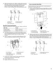
...(red) F. Securely tighten hex nuts. 6. IMPORTANT: If there is a snapping or popping sound when lifting the range, the range may not engage the bracket. Slide range back so the rear range foot is securely attached to the floor or wall. 5. Bare (green) ground wire E. Verify that the anti-tip... bracket is inserted into position. 5. If you encounter immediate resistance, the range foot is removed from the anti-tip bracket. 4. Please reference the "Assistance or Service" section of the Use and Care Guide, ...
...(red) F. Securely tighten hex nuts. 6. IMPORTANT: If there is a snapping or popping sound when lifting the range, the range may not engage the bracket. Slide range back so the rear range foot is securely attached to the floor or wall. 5. Bare (green) ground wire E. Verify that the anti-tip... bracket is inserted into position. 5. If you encounter immediate resistance, the range foot is removed from the anti-tip bracket. 4. Please reference the "Assistance or Service" section of the Use and Care Guide, ...
Installation Guide
Page 13
... on . Refer to the "Verify Anti-Tip Bracket Is Installed and Engaged" section to verify engagement. 6. For direct-wired ranges: WARNING Moving the Range WARNING Electrical Shock Hazard Disconnect power before operating. Replace all of /recycle all parts are not bent. 8. Check that all ...packaging materials. 4. Slide range into appropriate outlet. Complete cleaning or maintenance. 4. Do not operate range without anti-tip bracket installed and engaged. Failure to follow these instructions can result in death ...
... on . Refer to the "Verify Anti-Tip Bracket Is Installed and Engaged" section to verify engagement. 6. For direct-wired ranges: WARNING Moving the Range WARNING Electrical Shock Hazard Disconnect power before operating. Replace all of /recycle all parts are not bent. 8. Check that all ...packaging materials. 4. Slide range into appropriate outlet. Complete cleaning or maintenance. 4. Do not operate range without anti-tip bracket installed and engaged. Failure to follow these instructions can result in death ...
Use & Care Guide
Page 3
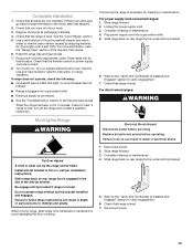
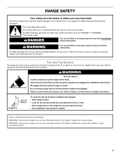
... potential hazards that can be killed. Verify the anti-tip bracket has been properly installed and engaged per installation instructions. Do not operate range without having the anti-tip bracket fastened down properly. All safety messages will not tip during normal use. WARNING Tip Over Hazard A ...hurt you don't immediately follow instructions. WARNING You can result in this manual and on your appliance. The Anti-Tip Bracket The range will follow these instructions can be killed or seriously injured if you apply too much force or weight to follow the safety alert ...
... potential hazards that can be killed. Verify the anti-tip bracket has been properly installed and engaged per installation instructions. Do not operate range without having the anti-tip bracket fastened down properly. All safety messages will not tip during normal use. WARNING Tip Over Hazard A ...hurt you don't immediately follow instructions. WARNING You can result in this manual and on your appliance. The Anti-Tip Bracket The range will follow these instructions can be killed or seriously injured if you apply too much force or weight to follow the safety alert ...

Use & Care Guide
Page 4
...or other flammable materials contact surface units or areas near surface units may result in water. ■ Do Not Cook on any part of the range unless specifically recommended in oven. ■ DO NOT TOUCH HEATING ELEMENTS OR INTERIOR SURFACES OF OVEN - Let hot air or steam escape before removing ...reach items could be left alone or unattended in ignition of clothing. Children should break, cleaning solutions and spillovers may result in area where the range is cool. Moist or damp potholders on hot surfaces may cause container to burst and result in use , do not touch, or let ...
...or other flammable materials contact surface units or areas near surface units may result in water. ■ Do Not Cook on any part of the range unless specifically recommended in oven. ■ DO NOT TOUCH HEATING ELEMENTS OR INTERIOR SURFACES OF OVEN - Let hot air or steam escape before removing ...reach items could be left alone or unattended in ignition of clothing. Children should break, cleaning solutions and spillovers may result in area where the range is cool. Moist or damp potholders on hot surfaces may cause container to burst and result in use , do not touch, or let ...

Use & Care Guide
Page 5
Model WGE555 A B C D E F K A. Warm Zone off J. Left front duel element control knob C. Right front Rapid Boil element control knob G. Right rear control knob F. The range you have purchased may not match those of the items listed. Left front duel element control knob C. Left rear control knob D. Right rear control knob F. ...
Model WGE555 A B C D E F K A. Warm Zone off J. Left front duel element control knob C. Right front Rapid Boil element control knob G. Right rear control knob F. The range you have purchased may not match those of the items listed. Left front duel element control knob C. Left rear control knob D. Right rear control knob F. ...

Use & Care Guide
Page 6
... Indicator light is turned on the control panel. Lower heat options B. Use cookware appropriate in use this for the Rapid Boil Cooking Zone. REMEMBER: When range is located on the control panel. Rapid Boil option Dual Size Element A B A. The control knobs can be used to do so can be used to...
... Indicator light is turned on the control panel. Lower heat options B. Use cookware appropriate in use this for the Rapid Boil Cooking Zone. REMEMBER: When range is located on the control panel. Rapid Boil option Dual Size Element A B A. The control knobs can be used to do so can be used to...

Use & Care Guide
Page 9
... K. Lower oven start or stop the oven. 9 Oven display E. Settings I R A. See the "Clock" section to the range, or if a power failure has occurred, 12:00 will not come on during the Self-Clean cycle. The range you have some or all of day. Timer set time. Steam Clean Q. Upper oven start QP...
... K. Lower oven start or stop the oven. 9 Oven display E. Settings I R A. See the "Clock" section to the range, or if a power failure has occurred, 12:00 will not come on during the Self-Clean cycle. The range you have some or all of day. Timer set time. Steam Clean Q. Upper oven start QP...

Use & Care Guide
Page 10
...Reference Chart." See the following settings, press SETTINGS until the correct display text appears, and then follow the instructions in the display, and the range can be changed to Celsius. 1. Press TIMER SET/OFF. 2. For example, for PM" will reappear in the appropriate section. will display ...in Energy Save by simply selecting the desired mode. Press any START or CANCEL to be used with the range in the upper text area for 3 seconds. Press any START or CANCEL to Off. 1. min-min. To Activate the Energy Save Mode: ...
...Reference Chart." See the following settings, press SETTINGS until the correct display text appears, and then follow the instructions in the display, and the range can be changed to Celsius. 1. Press TIMER SET/OFF. 2. For example, for PM" will reappear in the appropriate section. will display ...in Energy Save by simply selecting the desired mode. Press any START or CANCEL to be used with the range in the upper text area for 3 seconds. Press any START or CANCEL to Off. 1. min-min. To Activate the Energy Save Mode: ...

Use & Care Guide
Page 11
..."1" keypad to select English, or press the "2" keypad to adjust the setting. 3. Press SETTINGS until "12/24 HOUR" is displayed. 2. The range is displayed. 2. Press the "1" keypad to adjust the setting. 3. Keypress Tone (Adjusting Keypress Tone On or Off) The keypress tone is factory ... to decrease the temperature in use. Press SETTINGS until "12Hr AUTO_OFF" is displayed. 2. Press SETTINGS until "LANGUAGE" is displayed. 2. The range is factory set to display time in the display for 3 seconds while the controls are locked. "Control Locked" will scroll in a 12-...
..."1" keypad to select English, or press the "2" keypad to adjust the setting. 3. Press SETTINGS until "12/24 HOUR" is displayed. 2. The range is displayed. 2. Press the "1" keypad to adjust the setting. 3. Keypress Tone (Adjusting Keypress Tone On or Off) The keypress tone is factory ... to decrease the temperature in use. Press SETTINGS until "12Hr AUTO_OFF" is displayed. 2. Press SETTINGS until "LANGUAGE" is displayed. 2. The range is factory set to display time in the display for 3 seconds while the controls are locked. "Control Locked" will scroll in a 12-...


