
Installation Guide
Page 1
... 2 INSTALLATION REQUIREMENTS 3 Tools and Parts 3 Location Requirements 3 Electrical Requirements 5 Gas Supply Requirements 5 INSTALLATION INSTRUCTIONS 7 Unpack Range 7 Install Anti-Tip Bracket 7 Make Gas Connection 8 Verify Anti-Tip Bracket Is Installed and Engaged 9 Level Range 10 Electronic Ignition System 10 Warming Drawer or Premium Storage Drawer 12 Storage Drawer 12 Oven Door 13 Complete...
... 2 INSTALLATION REQUIREMENTS 3 Tools and Parts 3 Location Requirements 3 Electrical Requirements 5 Gas Supply Requirements 5 INSTALLATION INSTRUCTIONS 7 Unpack Range 7 Install Anti-Tip Bracket 7 Make Gas Connection 8 Verify Anti-Tip Bracket Is Installed and Engaged 9 Level Range 10 Electronic Ignition System 10 Warming Drawer or Premium Storage Drawer 12 Storage Drawer 12 Oven Door 13 Complete...

Installation Guide
Page 2
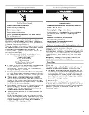
... the "What to reduce the chance of injury, and tell you don't immediately follow the safety alert symbol and either the word "DANGER" or "WARNING." RANGE SAFETY Your safety and the safety of others . WARNING: Gas leaks cannot always be killed or seriously injured if you what the potential hazard is...
... the "What to reduce the chance of injury, and tell you don't immediately follow the safety alert symbol and either the word "DANGER" or "WARNING." RANGE SAFETY Your safety and the safety of others . WARNING: Gas leaks cannot always be killed or seriously injured if you what the potential hazard is...

Installation Guide
Page 3
...connection must be used will not discolor, delaminate or sustain other damage. Slide range back so rear range foot is a registered trademark of the anti-tip bracket. Re-engage anti-tip bracket if range is required. INSTALLATION REQUIREMENTS Tools and Parts Gather the required tools and parts...the oven door. ■ Recessed installations must be sealed. ■ Do not seal the range to floor or wall. • Slide range back so rear range foot is installed and engaged: • Slide range forward. • Look for details. Thickness of combustion and ventilation air. ■ It is...
...connection must be used will not discolor, delaminate or sustain other damage. Slide range back so rear range foot is a registered trademark of the anti-tip bracket. Re-engage anti-tip bracket if range is required. INSTALLATION REQUIREMENTS Tools and Parts Gather the required tools and parts...the oven door. ■ Recessed installations must be sealed. ■ Do not seal the range to floor or wall. • Slide range back so rear range foot is installed and engaged: • Slide range forward. • Look for details. Thickness of combustion and ventilation air. ■ It is...
Installation Guide
Page 4
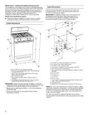
...cm) minimum when bottom of wood or metal cabinet is not applicable, use the Standard for dimensional clearances above the range, follow the range hood or microwave hood combination installation instructions for Manufactured Home Installations, ANSI A225.1/NFPA 501A or with local codes. ...Cabinet Dimensions Cabinet opening width F. upper cabinet depth C. 30" (76.2 cm) min. The shaded areas are for installation of this range must conform to side wall or other combustible material. Grounded outlet N. opening width D. When such standard is covered by adjusting the leveling...
...cm) minimum when bottom of wood or metal cabinet is not applicable, use the Standard for dimensional clearances above the range, follow the range hood or microwave hood combination installation instructions for Manufactured Home Installations, ANSI A225.1/NFPA 501A or with local codes. ...Cabinet Dimensions Cabinet opening width F. upper cabinet depth C. 30" (76.2 cm) min. The shaded areas are for installation of this range must conform to side wall or other combustible material. Grounded outlet N. opening width D. When such standard is covered by adjusting the leveling...
Installation Guide
Page 5
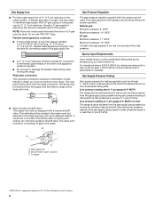
... without consulting the serving gas supplier. It is recommended that you are necessary. It is recommended that a separate circuit serving only this range will not be affected if operated on the model/serial rating plate for use an adapter. If connected to LP, have a qualified ..."Gas Conversions" section. 5 However, occasional nuisance tripping of the GFCI breaker is possible due to the normal operating nature of electronic gas ranges. ■ The wiring diagram is located on the types of gas that is not properly polarized. Securely tighten all governing codes and ordinances...
... without consulting the serving gas supplier. It is recommended that you are necessary. It is recommended that a separate circuit serving only this range will not be affected if operated on the model/serial rating plate for use an adapter. If connected to LP, have a qualified ..."Gas Conversions" section. 5 However, occasional nuisance tripping of the GFCI breaker is possible due to the normal operating nature of electronic gas ranges. ■ The wiring diagram is located on the types of gas that is not properly polarized. Securely tighten all governing codes and ordinances...
Installation Guide
Page 6
...follows for turning on longer runs may be equipped with a manual shutoff valve. Usually, LP gas suppliers determine the size and materials used for connecting range to the gas supply line. ■ A ½" (1.3 cm) male pipe thread is for proper operation: Natural gas: Minimum pressure: 5" ...isolated from the gas supply piping system by closing . A C A. Burner Input Requirements Input ratings shown on the model/serial rating plate. To range †®TEFLON is a registered trademark of 4% for each 1,000 ft (304.8 m) above the manifold pressure shown on the model/serial ...
...follows for turning on longer runs may be equipped with a manual shutoff valve. Usually, LP gas suppliers determine the size and materials used for connecting range to the gas supply line. ■ A ½" (1.3 cm) male pipe thread is for proper operation: Natural gas: Minimum pressure: 5" ...isolated from the gas supply piping system by closing . A C A. Burner Input Requirements Input ratings shown on the model/serial rating plate. To range †®TEFLON is a registered trademark of 4% for each 1,000 ft (304.8 m) above the manifold pressure shown on the model/serial ...

Installation Guide
Page 7
... wall per installation instructions. Rear leveling leg C. Install anti-tip bracket to lower the rear leveling legs one-half turn . If you are installing the range in death or serious burns to the floor. 3. Front leveling leg 7 Shipping base 4. AD C B A. ¼" drive ratchet B. C A Install ...side of the determined mounting method. Bracket V-notch 4. See the following illustrations. B A. Wrench or pliers C. Re-engage anti-tip bracket if range is taped inside oven. 3. Failure to follow these instructions can result in a mobile home, you can result in the slot of the cutout...
... wall per installation instructions. Rear leveling leg C. Install anti-tip bracket to lower the rear leveling legs one-half turn . If you are installing the range in death or serious burns to the floor. 3. Front leveling leg 7 Shipping base 4. AD C B A. ¼" drive ratchet B. C A Install ...side of the determined mounting method. Bracket V-notch 4. See the following illustrations. B A. Wrench or pliers C. Re-engage anti-tip bracket if range is taped inside oven. 3. Failure to follow these instructions can result in a mobile home, you can result in the slot of the cutout...

Installation Guide
Page 8
...joint compound made for use with the two #12 x 1⁵⁄₈" screws provided. 6. Remove shipping base, cardboard or hardboard from under range. 7. If connected to the wall or floor with LP gas to the existing gas line. Union J. 90° elbow Typical flexible connection 1. ...Front position Diagonal (2 options) 5. Using the Phillips screwdriver, mount anti-tip bracket to LP, have ½" male pipe thread) C. Move range into its final location, making sure rear leveling leg slides into anti-tip bracket. 8. Explosion Hazard Use a new CSA International approved gas supply ...
...joint compound made for use with the two #12 x 1⁵⁄₈" screws provided. 6. Remove shipping base, cardboard or hardboard from under range. 7. If connected to the wall or floor with LP gas to the existing gas line. Union J. 90° elbow Typical flexible connection 1. ...Front position Diagonal (2 options) 5. Using the Phillips screwdriver, mount anti-tip bracket to LP, have ½" male pipe thread) C. Move range into its final location, making sure rear leveling leg slides into anti-tip bracket. 8. Explosion Hazard Use a new CSA International approved gas supply ...

Installation Guide
Page 9
... E A. Use pipe-joint compound. H. Gas pressure regulator shutoff valve shown in the anti-tip bracket. 3. See "Storage Drawer" section. 2. On Ranges with a Storage Drawer: 1. A. If burner caps are not properly positioned, surface burners will not light. Burner cap C. C. Do not use an ...Connection 1. Open the manual shutoff valve in the anti-tip bracket. 9 Remove cooktop burner caps and grates from parts package. The range foot is in the "on an approved noncorrosive leak-detection solution. A B WARNING Electrical Shock Hazard Plug into a grounded 3 prong...
... E A. Use pipe-joint compound. H. Gas pressure regulator shutoff valve shown in the anti-tip bracket. 3. See "Storage Drawer" section. 2. On Ranges with a Storage Drawer: 1. A. If burner caps are not properly positioned, surface burners will not light. Burner cap C. C. Do not use an ...Connection 1. Open the manual shutoff valve in the anti-tip bracket. 9 Remove cooktop burner caps and grates from parts package. The range foot is in the "on an approved noncorrosive leak-detection solution. A B WARNING Electrical Shock Hazard Plug into a grounded 3 prong...
Installation Guide
Page 10
...Clean functions. Repeat start-up or down until rear leveling leg is more than 2" (5.1 cm) from sliding into the slot of the range, first side to "Off" and contact your dealer or authorized service company for satisfactory baking performance and best cleaning results using the adjustment ...screw in place of the User Instructions, for contact information. 6. If range is not level, pull range forward until the range is engaged in the anti-tip bracket. Low flame B. The valve stem is securely attached to light the burner....
...Clean functions. Repeat start-up or down until rear leveling leg is more than 2" (5.1 cm) from sliding into the slot of the range, first side to "Off" and contact your dealer or authorized service company for satisfactory baking performance and best cleaning results using the adjustment ...screw in place of the User Instructions, for contact information. 6. If range is not level, pull range forward until the range is engaged in the anti-tip bracket. Low flame B. The valve stem is securely attached to light the burner....

Installation Guide
Page 11
... in character. Screwdriver C. Pliers 1. Hold the knob stem with an outer mantle of dark blue, and should have a ½" (1.3 cm) long inner cone of the range. Remove the oven rack. 2. A 4. This flame should be adjusted: A B C A. Using a mirror: Insert a mirror to one side of Oven Broil Burner 1. Adjust Oven Broil Burner Flame...
... in character. Screwdriver C. Pliers 1. Hold the knob stem with an outer mantle of dark blue, and should have a ½" (1.3 cm) long inner cone of the range. Remove the oven rack. 2. A 4. This flame should be adjusted: A B C A. Using a mirror: Insert a mirror to one side of Oven Broil Burner 1. Adjust Oven Broil Burner Flame...

Installation Guide
Page 12
... premium storage drawer is cool and empty. Lift up the drawer alignment tab from inside the warming drawer or premium storage drawer, and allow the range to cool completely before attempting to the drawer stop notch 2. Adjust the air shutter as needed. 3. Tighten lock screw. Place the rear alignment tabs into...
... premium storage drawer is cool and empty. Lift up the drawer alignment tab from inside the warming drawer or premium storage drawer, and allow the range to cool completely before attempting to the drawer stop notch 2. Adjust the air shutter as needed. 3. Tighten lock screw. Place the rear alignment tabs into...

Installation Guide
Page 13
... not tip when items are now installed. If there is connected. ■ See "Troubleshooting" in the drawer. See "Level Range." 5. A. Oven Door For normal range use, it is heavy. Complete Installation 1. Check that all of liquid household cleaner and warm water to the locked position. Dispose..., check for heat. Slowly push the drawer into the door. Lift the oven door while holding both hanger arms into the range. When the range has been on range operation. Engage drawer glide. You should hear a "click" as outlined above. ■ If the gas supply line shutoff valve...
... not tip when items are now installed. If there is connected. ■ See "Troubleshooting" in the drawer. See "Level Range." 5. A. Oven Door For normal range use, it is heavy. Complete Installation 1. Check that all of liquid household cleaner and warm water to the locked position. Dispose..., check for heat. Slowly push the drawer into the door. Lift the oven door while holding both hanger arms into the range. When the range has been on range operation. Engage drawer glide. You should hear a "click" as outlined above. ■ If the gas supply line shutoff valve...
Installation Guide
Page 14
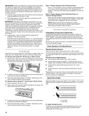
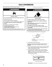
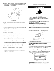
...Hazard A child or adult can result in death or serious burns to floor or wall per installation instructions. Gas supply line 2. Unplug range or disconnect power. Locate gas pressure regulator at rear of a qualified person include: licensed heating personnel, authorized gas company personnel, and ...Remove storage drawer, warming drawer or premium storage drawer. To Convert Gas Pressure Regulator (Natural Gas to do so can tip the range and be done by a qualified installer. LP Gas Conversion WARNING WARNING Explosion Hazard Use a new CSA International approved gas supply ...
...Hazard A child or adult can result in death or serious burns to floor or wall per installation instructions. Gas supply line 2. Unplug range or disconnect power. Locate gas pressure regulator at rear of a qualified person include: licensed heating personnel, authorized gas company personnel, and ...Remove storage drawer, warming drawer or premium storage drawer. To Convert Gas Pressure Regulator (Natural Gas to do so can tip the range and be done by a qualified installer. LP Gas Conversion WARNING WARNING Explosion Hazard Use a new CSA International approved gas supply ...

Installation Guide
Page 15
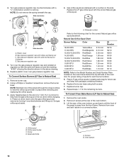
... "!LP" is facing the direction shown in the nut driver while changing it counterclockwise and lifting out. NOTE: Reinstall one of the screws through the range cooktop to help hold the orifice spud holder in the hex area. C A D B B A. Spark electrode 4. A A. A. Press nut driver down onto the gas orifice spud and remove...
... "!LP" is facing the direction shown in the nut driver while changing it counterclockwise and lifting out. NOTE: Reinstall one of the screws through the range cooktop to help hold the orifice spud holder in the hex area. C A D B B A. Spark electrode 4. A A. A. Press nut driver down onto the gas orifice spud and remove...
Installation Guide
Page 17
... child or adult can result in death or serious burns to save the orifices that have to the closed " position C. Do not operate range without anti-tip bracket installed and engaged. Manual shutoff valve "closed position. See the "Storage Drawer" or "Warming Drawer or Premium Storage..." hood. Replace the oven racks. Checking for each cooktop burner. Refer to ½" (1.3 cm) long. Slide range back so rear range foot is very important. To range B. To Convert Gas Pressure Regulator (LP Gas to access the gas pressure regulator. Remove plastic cover from gas pressure ...
... child or adult can result in death or serious burns to save the orifices that have to the closed " position C. Do not operate range without anti-tip bracket installed and engaged. Manual shutoff valve "closed position. See the "Storage Drawer" or "Warming Drawer or Premium Storage..." hood. Replace the oven racks. Checking for each cooktop burner. Refer to ½" (1.3 cm) long. Slide range back so rear range foot is very important. To range B. To Convert Gas Pressure Regulator (LP Gas to access the gas pressure regulator. Remove plastic cover from gas pressure ...
Installation Guide
Page 18
Gas orifice spuds are stamped with package containing literature. 6. NOTE: Reinstall one of the screws through the range cooktop to the following chart for each burner location. 5. Press nut driver down onto the gas orifice spud and remove by turning it aside on ...
Gas orifice spuds are stamped with package containing literature. 6. NOTE: Reinstall one of the screws through the range cooktop to the following chart for each burner location. 5. Press nut driver down onto the gas orifice spud and remove by turning it aside on ...
Installation Guide
Page 20
... the "Oven Door" section. 9. Refer to the "Make Gas Connection" section for properly connecting the range to the "Electronic Ignition System" section for each cooktop burner. Refer to "Complete Installation" in the "Installation Instructions" section of Whirlpool, U.S.A. 1/12 Printed in the rear of the oven and attach it with 2 screws. 7. Position the...
... the "Oven Door" section. 9. Refer to the "Make Gas Connection" section for properly connecting the range to the "Electronic Ignition System" section for each cooktop burner. Refer to "Complete Installation" in the "Installation Instructions" section of Whirlpool, U.S.A. 1/12 Printed in the rear of the oven and attach it with 2 screws. 7. Position the...
Use & Care Guide
Page 1
... a problem not covered in TROUBLESHOOTING, please visit our website at 1-800-253-1301. You will need assistance, call us at www.whirlpool.com for purchasing this high-quality product. If you still need your model and serial number located on the oven frame behind the top... left side of Contents RANGE SAFETY 2 The Anti-Tip Bracket 3 FEATURE GUIDE 4 COOKTOP USE 5 Sealed Surface Burners 5 Burner Size 6 Cookware 6 Home Canning 7 OVEN USE 7 Electronic Oven ...
... a problem not covered in TROUBLESHOOTING, please visit our website at 1-800-253-1301. You will need assistance, call us at www.whirlpool.com for purchasing this high-quality product. If you still need your model and serial number located on the oven frame behind the top... left side of Contents RANGE SAFETY 2 The Anti-Tip Bracket 3 FEATURE GUIDE 4 COOKTOP USE 5 Sealed Surface Burners 5 Burner Size 6 Cookware 6 Home Canning 7 OVEN USE 7 Electronic Oven ...

Use & Care Guide
Page 2
... the potential hazard is the safety alert symbol. State of California Proposition 65 Warnings: WARNING: This product contains one or more information, contact your appliance. RANGE SAFETY Your safety and the safety of California to cause cancer. Do not store or use gasoline or other flammable vapors and liquids in the...
... the potential hazard is the safety alert symbol. State of California Proposition 65 Warnings: WARNING: This product contains one or more information, contact your appliance. RANGE SAFETY Your safety and the safety of California to cause cancer. Do not store or use gasoline or other flammable vapors and liquids in the...


