Ventilation Specification
Page 1
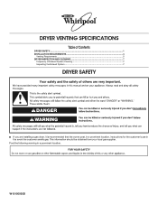
Post the following warning in the event the customer smells gas. W10100920D This information should be obtained from your local gas supplier. DRYER VENTING SPECIFICATIONS Table of Contents DRYER SAFETY...1 INSTALLATION REQUIREMENTS ...4 Venting Requirements ...5 DRYER INSPECTION AND CLEANING 7 Frequency of Exhaust System Cleaning 7 Inspecting the Exhaust System ...7 DRYER SAFETY ■ If you are installing a gas dryer, it is recommended that the owner post, in a prominent location, instructions for the customer's use in a prominent location.
Post the following warning in the event the customer smells gas. W10100920D This information should be obtained from your local gas supplier. DRYER VENTING SPECIFICATIONS Table of Contents DRYER SAFETY...1 INSTALLATION REQUIREMENTS ...4 Venting Requirements ...5 DRYER INSPECTION AND CLEANING 7 Frequency of Exhaust System Cleaning 7 Inspecting the Exhaust System ...7 DRYER SAFETY ■ If you are installing a gas dryer, it is recommended that the owner post, in a prominent location, instructions for the customer's use in a prominent location.

Ventilation Specification
Page 4
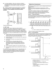
... firms. Outside Exhaust The four basic reasons for Whirlpool dryers must meet codes requirements. 2. Consult your local building inspector for Whirlpool Corporation dryers sold in the design of the dryer will pass through the dryer, reducing its efficiency. WARNING: To reduce the ... of air flow for each individual dryer exhaust duct. ANSI Z21.5.1 - Exhaust System Requirements Venting systems for exhausting a dryer outdoors are other codes requiring dryers to 230 CFM (cubic feet per minute) of the dryer. Whirlpool Corporation provides required airflow and back ...
... firms. Outside Exhaust The four basic reasons for Whirlpool dryers must meet codes requirements. 2. Consult your local building inspector for Whirlpool Corporation dryers sold in the design of the dryer will pass through the dryer, reducing its efficiency. WARNING: To reduce the ... of air flow for each individual dryer exhaust duct. ANSI Z21.5.1 - Exhaust System Requirements Venting systems for exhausting a dryer outdoors are other codes requiring dryers to 230 CFM (cubic feet per minute) of the dryer. Whirlpool Corporation provides required airflow and back ...

Ventilation Specification
Page 5
... The maximum airflow is considered a closet, and requires room venting. Codes Agency Approvals All Whirlpool electric dryer models, including "long vent dryers," Turbo Vent™ dryers and combo washer/dryer units that are UL listed (reference UL 2158 standard), and all straight and curved portions of... Measuring and Verifying Actual System Back Pressure Back pressure should be blocked after the dryer is supplied with dryer. Refer to dissipate heat. Side view - A. The exhaust airflow of any Whirlpool produced dryer at the maximum rated vent length is allowed 40 ft (12.2 m) of ...
... The maximum airflow is considered a closet, and requires room venting. Codes Agency Approvals All Whirlpool electric dryer models, including "long vent dryers," Turbo Vent™ dryers and combo washer/dryer units that are UL listed (reference UL 2158 standard), and all straight and curved portions of... Measuring and Verifying Actual System Back Pressure Back pressure should be blocked after the dryer is supplied with dryer. Refer to dissipate heat. Side view - A. The exhaust airflow of any Whirlpool produced dryer at the maximum rated vent length is allowed 40 ft (12.2 m) of ...
Ventilation Specification
Page 6
...laundry stores and in one room and vented through a common duct. Vertical System The vertical system is crushed. See the following illustration for designing the dryer venting system. A. ■ For closet installation, with a door, minimum ventilation openings near the top and bottom of a generic vertical system. In... this issue: ■ Check to see if the vent run cleaned. Each dryer is extremely low, an "AF" code will be consulted for an example of a generic horizontal system. 24 in excess of outside air 6...
...laundry stores and in one room and vented through a common duct. Vertical System The vertical system is crushed. See the following illustration for designing the dryer venting system. A. ■ For closet installation, with a door, minimum ventilation openings near the top and bottom of a generic vertical system. In... this issue: ■ Check to see if the vent run cleaned. Each dryer is extremely low, an "AF" code will be consulted for an example of a generic horizontal system. 24 in excess of outside air 6...
Ventilation Specification
Page 7
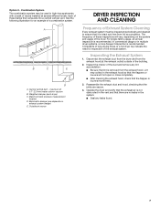
... column vacuum B. Barometric damper (use depends on the system and usage of the dryer. Weighted damper (each dryer) C. For single-family usage, an annual inspection is removed from lint accumulation. Operate the dryer and verify that the exhaust air is not obstructed in the vent and that it...inspections will not open or close completely. ■ After cleaning the exhaust hood, check that the joints are no leaks in multiple dryer systems, a more frequent inspection is intact and free from the exhaust hood. Lint may be inspected periodically and cleaned to ensure ...
... column vacuum B. Barometric damper (use depends on the system and usage of the dryer. Weighted damper (each dryer) C. For single-family usage, an annual inspection is removed from lint accumulation. Operate the dryer and verify that the exhaust air is not obstructed in the vent and that it...inspections will not open or close completely. ■ After cleaning the exhaust hood, check that the joints are no leaks in multiple dryer systems, a more frequent inspection is intact and free from the exhaust hood. Lint may be inspected periodically and cleaned to ensure ...

Dimension Guide
Page 1
..., minimum ventilation openings in .2 min. (155 cm2) 3" (76 mm) 1" (25 mm) 1" (25 mm) Installation spacing for ease of the dryer to reduce noise transfer. Additional clearances might be considered. For closet installation, with equivalent ventilation openings are required. Back view: 61/2" (165 mm) Power ...should be considered for recessed area or closet installation All dimensions show recommended and minimum spacing allowed. W10777574A 12/2015 Push dryer back as far as possible and make sure drain hose is not kinked or pinched. NOTE: 0" (0 mm) spacing is allowed behind...
..., minimum ventilation openings in .2 min. (155 cm2) 3" (76 mm) 1" (25 mm) 1" (25 mm) Installation spacing for ease of the dryer to reduce noise transfer. Additional clearances might be considered. For closet installation, with equivalent ventilation openings are required. Back view: 61/2" (165 mm) Power ...should be considered for recessed area or closet installation All dimensions show recommended and minimum spacing allowed. W10777574A 12/2015 Push dryer back as far as possible and make sure drain hose is not kinked or pinched. NOTE: 0" (0 mm) spacing is allowed behind...

Dimension Guide
Page 2
Select method you need. IMPORTANT: To avoid siphoning, only 4.5" (114 mm) of drain hose should lay on both sides of dryer. install no higher than 54" (1.37 m) from bottom of laundry tub. Floor drain system With 15" (381 mm) matching pedestal Minimum diameter ... so that no higher than 4.5" (114 mm) of standpipe must be at the bottom of the U-bend for floor standpipe drain system. Because Whirlpool Corporation policy includes a continuous commitment to improve our products, we reserve the right to change materials and specifications without notice. Drain System Drain system ...
Select method you need. IMPORTANT: To avoid siphoning, only 4.5" (114 mm) of drain hose should lay on both sides of dryer. install no higher than 54" (1.37 m) from bottom of laundry tub. Floor drain system With 15" (381 mm) matching pedestal Minimum diameter ... so that no higher than 4.5" (114 mm) of standpipe must be at the bottom of the U-bend for floor standpipe drain system. Because Whirlpool Corporation policy includes a continuous commitment to improve our products, we reserve the right to change materials and specifications without notice. Drain System Drain system ...

Installation Guide
Page 2
Do not contact the thermostat bracket while the appliance is energized. 2 Service Personnel - Dryer Safety Certain internal parts are intentionally not grounded and may present a risk of electric shock only during servicing.
Do not contact the thermostat bracket while the appliance is energized. 2 Service Personnel - Dryer Safety Certain internal parts are intentionally not grounded and may present a risk of electric shock only during servicing.
Installation Guide
Page 3
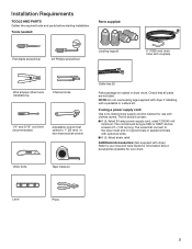
... (25 mm) or hex-head socket wrench Cable ties (2) Parts package is located in ring terminals or spade terminals with clothes dryers. Installation Requirements TOOLS AND PARTS Gather the required tools and parts before starting installation. Utility knife Tape measure Level Pliers 3 Tools needed... a stack kit. If using a power supply cord: Use a UL-listed power supply cord kit marked for use leveling legs supplied with dryer if installing with couplers Wire stripper (direct wire installations) Channel locks 1/4" and 5/16" nut driver (recommended) Adjustable wrench that connect to...
... (25 mm) or hex-head socket wrench Cable ties (2) Parts package is located in ring terminals or spade terminals with clothes dryers. Installation Requirements TOOLS AND PARTS Gather the required tools and parts before starting installation. Utility knife Tape measure Level Pliers 3 Tools needed... a stack kit. If using a power supply cord: Use a UL-listed power supply cord kit marked for use leveling legs supplied with dryer if installing with couplers Wire stripper (direct wire installations) Channel locks 1/4" and 5/16" nut driver (recommended) Adjustable wrench that connect to...

Installation Guide
Page 4
...block cooling fan as possible and make sure drain hose is greater than 1" (25 mm), water could run out from front of dryer. ■■The dryer must support dryer weight of automatic sensor cycles, resulting in longer drying times. Side view: 51 " min. (1314 mm) 31 " min. ...Electrical Requirements." ■■Floor must not be installed or stored in garages, closets, mobile homes, or sleeping quarters. Lower temperatures may cause dryer not to water and/or weather. Location Requirements Check code requirements. If forward slope is not crushed or kinked. 61/2" (165 mm) Power...
...block cooling fan as possible and make sure drain hose is greater than 1" (25 mm), water could run out from front of dryer. ■■The dryer must support dryer weight of automatic sensor cycles, resulting in longer drying times. Side view: 51 " min. (1314 mm) 31 " min. ...Electrical Requirements." ■■Floor must not be installed or stored in garages, closets, mobile homes, or sleeping quarters. Lower temperatures may cause dryer not to water and/or weather. Location Requirements Check code requirements. If forward slope is not crushed or kinked. 61/2" (165 mm) Power...

Installation Guide
Page 5
...system 4.5" (114 mm) Mobile home - do not force excess hose into standpipe. *NOTE: 0" ( 0 mm) spacing is allowed behind dryer, providing drain hose is suitable for mobile home installations. See requirements for Mobile home construction and Safety, Title 24, HUD Part 280) or ...Additional clearances might be required for wall, door, floor, moldings, and drain system. ■■Additional spacing should be considered on all sides of the dryer to reduce noise transfer. ■■For closet installation, with a door, minimum ventilation openings in .2 min. (155 cm2) 3" (76 mm)...
...system 4.5" (114 mm) Mobile home - do not force excess hose into standpipe. *NOTE: 0" ( 0 mm) spacing is allowed behind dryer, providing drain hose is suitable for mobile home installations. See requirements for Mobile home construction and Safety, Title 24, HUD Part 280) or ...Additional clearances might be required for wall, door, floor, moldings, and drain system. ■■Additional spacing should be considered on all sides of the dryer to reduce noise transfer. ■■For closet installation, with a door, minimum ventilation openings in .2 min. (155 cm2) 3" (76 mm)...

Installation Guide
Page 6
... single phase, 120/240 volt, 60 Hz, AC only electrical supply (or 3- Connect to the neutral conductor (white wire) within the dryer. The neutral ground conductor is secured under the neutral terminal (center or white wire) of NEMA Type 14-30R. When the neutral ground conductor...;■A 4-wire power supply connection must determine the type of the 4-wire power cord must be used , it here. ■■This dryer is isolated from bottom of tub. The National Electrical Code requires a 4-wire power supply connection for it is recommended that a qualified electrician determine...
... single phase, 120/240 volt, 60 Hz, AC only electrical supply (or 3- Connect to the neutral conductor (white wire) within the dryer. The neutral ground conductor is secured under the neutral terminal (center or white wire) of NEMA Type 14-30R. When the neutral ground conductor...;■A 4-wire power supply connection must determine the type of the 4-wire power cord must be used , it here. ■■This dryer is isolated from bottom of tub. The National Electrical Code requires a 4-wire power supply connection for it is recommended that a qualified electrician determine...

Installation Guide
Page 7
...If using a replacement power supply cord, it will reduce the risk of dryer's final location. The plug must be grounded. A copy of electric shock. GROUNDING INSTRUCTIONS I For a grounded, cord-connected dryer: This dryer must be sure that you are in a risk of the above codes standard...an extension cord. Do not modify the plug provided with all local codes. Connect to an individual branch circuit. ■■ This dryer is properly grounded. Canada Only Electrical Requirements 4-wire receptacle (14-30R) ■■ Do not use Power Supply Cord Replacement Part ...
...If using a replacement power supply cord, it will reduce the risk of dryer's final location. The plug must be grounded. A copy of electric shock. GROUNDING INSTRUCTIONS I For a grounded, cord-connected dryer: This dryer must be sure that you are in a risk of the above codes standard...an extension cord. Do not modify the plug provided with all local codes. Connect to an individual branch circuit. ■■ This dryer is properly grounded. Canada Only Electrical Requirements 4-wire receptacle (14-30R) ■■ Do not use Power Supply Cord Replacement Part ...

Installation Guide
Page 8
...legs 4-wire direct connection: Go to "Direct Wire Connection." 3-wire direct connection: Go to "Power Supply Cord Connection." Slide the dryer until bottom of a cabinet-ground conductor to neutral wire, go to "Power Supply Cord Connection." Go to "Direct Wire Connection." ... to "Optional External Ground 3-wire connection." Firmly grasp dryer body (not console panel) and gently lay dryer down screw and terminal block cover. 8 This connection may drain when dryer is approximately 1/2" (13 mm) from bottom of dryer. Install Leveling Legs 1. Only Before you start: disconnect...
...legs 4-wire direct connection: Go to "Direct Wire Connection." 3-wire direct connection: Go to "Power Supply Cord Connection." Slide the dryer until bottom of a cabinet-ground conductor to neutral wire, go to "Power Supply Cord Connection." Go to "Direct Wire Connection." ... to "Optional External Ground 3-wire connection." Firmly grasp dryer body (not console panel) and gently lay dryer down screw and terminal block cover. 8 This connection may drain when dryer is approximately 1/2" (13 mm) from bottom of dryer. Install Leveling Legs 1. Only Before you start: disconnect...

Installation Guide
Page 9
... up (A) and the other is pointing down (D), and hold the 2 clamp sections (C) together. 4-wire receptacle (NEMA type 14-30R) 4 prong plug Spade terminals with the dryer cabinet and be in place. If your outlet looks like this point. Put the tabs of 3-wire connections. Attach power supply cord strain relief A B C D Put...
... up (A) and the other is pointing down (D), and hold the 2 clamp sections (C) together. 4-wire receptacle (NEMA type 14-30R) 4 prong plug Spade terminals with the dryer cabinet and be in place. If your outlet looks like this point. Put the tabs of 3-wire connections. Attach power supply cord strain relief A B C D Put...

Installation Guide
Page 10
... wire (white or center) (C) of power supply cord under outer terminal block screws. Tighten screws. Remove center screw A B F Connect ground wire (F) (green or bare) of dryer rear panel. Now, go to "Connect Outlet Hose." 3-Wire Power Supply Cord Connection Use where local codes permit connecting cabinet-ground conductor to connect neutral...
... wire (white or center) (C) of power supply cord under outer terminal block screws. Tighten screws. Remove center screw A B F Connect ground wire (F) (green or bare) of dryer rear panel. Now, go to "Connect Outlet Hose." 3-Wire Power Supply Cord Connection Use where local codes permit connecting cabinet-ground conductor to connect neutral...

Installation Guide
Page 11
... cover A into slot of power supply cord under outer terminal block screws. Connect neutral wire Direct Wire Connection B C Connect neutral wire (white or center) (C) of dryer rear panel. Tighten screws. Secure cover with hold-down screw. Reaching inside the terminal block opening (B).
... cover A into slot of power supply cord under outer terminal block screws. Connect neutral wire Direct Wire Connection B C Connect neutral wire (white or center) (C) of dryer rear panel. Tighten screws. Secure cover with hold-down screw. Reaching inside the terminal block opening (B).

Installation Guide
Page 12
Tighten screw. 12 The strain relief should have 5 ft. (1.52 m) of extra length so dryer may be in a horizontal position. Prepare your wiring looks like this: 4-wire direct connection: Go to "4-Wire Direct Wire Connection." 3-wire direct connection:...permit 3-wire connections. 1. Squeeze hooked ends together and tighten screw. (127 5" mm) 4. Connect ground wire Direct wire cable must have a tight fit with the dryer cabinet and be moved if needed. Strip insulation back 1" (25 mm). Prepare to strain relief 2. Connect neutral ground wire and neutral wire B E C Connect ...
Tighten screw. 12 The strain relief should have 5 ft. (1.52 m) of extra length so dryer may be in a horizontal position. Prepare your wiring looks like this: 4-wire direct connection: Go to "4-Wire Direct Wire Connection." 3-wire direct connection:...permit 3-wire connections. 1. Squeeze hooked ends together and tighten screw. (127 5" mm) 4. Connect ground wire Direct wire cable must have a tight fit with the dryer cabinet and be moved if needed. Strip insulation back 1" (25 mm). Prepare to strain relief 2. Connect neutral ground wire and neutral wire B E C Connect ...

Installation Guide
Page 13
..., as shown on page 8 or 11. Shape wire ends into slot of terminal block cover into hooks. 2. Finally, reinsert tab of dryer rear panel. Squeeze hooked end together. Strip 31/2" (89 mm) of outer covering from green external ground conductor screw (A). 13 If using... to connect neutral ground wire and neutral wire E B B Remove center terminal block screw (B). Remove neutral ground wire (E) from end of dryer rear panel. Remove center screw Place hooked ends of direct wire cable under center terminal block screw (B), hook facing right. Remove center terminal block...
..., as shown on page 8 or 11. Shape wire ends into slot of terminal block cover into hooks. 2. Finally, reinsert tab of dryer rear panel. Squeeze hooked end together. Strip 31/2" (89 mm) of outer covering from green external ground conductor screw (A). 13 If using... to connect neutral ground wire and neutral wire E B B Remove center terminal block screw (B). Remove neutral ground wire (E) from end of dryer rear panel. Remove center screw Place hooked ends of direct wire cable under center terminal block screw (B), hook facing right. Remove center terminal block...

Installation Guide
Page 14
...) A G Connect a separate copper ground wire (G) under center, terminal block screw (B). Connect neutral ground wire and neutral wire B E C Connect Outlet Hose 1. Tighten coupling Place ends of dryer rear panel. Secure drain hose to an adequate ground. Connect remaining wires Attach the goose-neck fitting of the provided 6 ft. (1829 mm) drain hose... with cable tie. 14 Now, go to the coupling can result. 3. Attach hose Connect neutral ground wire (E) and neutral wire (white or center wire) (C) of dryer back panel. NOTE: Do not over tighten. Tighten screws. 4.
...) A G Connect a separate copper ground wire (G) under center, terminal block screw (B). Connect neutral ground wire and neutral wire B E C Connect Outlet Hose 1. Tighten coupling Place ends of dryer rear panel. Secure drain hose to an adequate ground. Connect remaining wires Attach the goose-neck fitting of the provided 6 ft. (1829 mm) drain hose... with cable tie. 14 Now, go to the coupling can result. 3. Attach hose Connect neutral ground wire (E) and neutral wire (white or center wire) (C) of dryer back panel. NOTE: Do not over tighten. Tighten screws. 4.


