Installation Instructions
Page 2
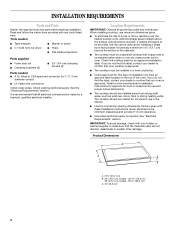
.... See the "Electrical Requirements" section. INSTALLATION REQUIREMENTS Tools and Parts Gather the required tools and parts before starting installation. When installing cooktop, use and proper cutout dimensions. ■ The cooktop should be installed either alone or over the heated surface units, cabinet storage space located above the surface units should be...
.... See the "Electrical Requirements" section. INSTALLATION REQUIREMENTS Tools and Parts Gather the required tools and parts before starting installation. When installing cooktop, use and proper cutout dimensions. ■ The cooktop should be installed either alone or over the heated surface units, cabinet storage space located above the surface units should be...
Installation Instructions
Page 3
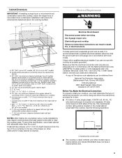
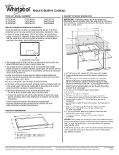
...Combustible area above countertop (shown by not less than ¹⁄₄" [0.6 cm] flame retardant millboard covered with not less than the cutout. To avoid this modification, use a base cabinet with a qualified electrical installer if you are adequate and in base cabinet is required....determine the type of the above ) C. 30" (76.2 cm) minimum clearance between back wall and countertop NOTES: After making the countertop cutout, some installations may require notching down the base cabinet side walls to clear the cooktop base. Model W5CE3024 does not have a neutral (...
...Combustible area above countertop (shown by not less than ¹⁄₄" [0.6 cm] flame retardant millboard covered with not less than the cutout. To avoid this modification, use a base cabinet with a qualified electrical installer if you are adequate and in base cabinet is required....determine the type of the above ) C. 30" (76.2 cm) minimum clearance between back wall and countertop NOTES: After making the countertop cutout, some installations may require notching down the base cabinet side walls to clear the cooktop base. Model W5CE3024 does not have a neutral (...
Installation Instructions
Page 4
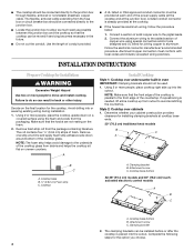
... strip adhesive-side down on uneven counters. NOTE: Make sure that the front edge of the cooktop is needed, lift entire cooktop up into the cutout. Cooktop A. Clamping bracket B. Cooktop base bottom B. Aluminum/copper connection must be provided at the junction box). Decide on the foam. 2. Using 2 or ... special connectors and/or tools designed and UL listed for joining copper to the added section of copper wire using the foam end posts from cutout to do so can result in back or other injury. Cooktop base B. ¼" (0.64 cm) Foam strip C. Cooktop base bottom All 36" (91...
... strip adhesive-side down on uneven counters. NOTE: Make sure that the front edge of the cooktop is needed, lift entire cooktop up into the cutout. Cooktop A. Clamping bracket B. Cooktop base bottom B. Aluminum/copper connection must be provided at the junction box). Decide on the foam. 2. Using 2 or ... special connectors and/or tools designed and UL listed for joining copper to the added section of copper wire using the foam end posts from cutout to do so can result in back or other injury. Cooktop base B. ¼" (0.64 cm) Foam strip C. Cooktop base bottom All 36" (91...
Installation Instructions
Page 5
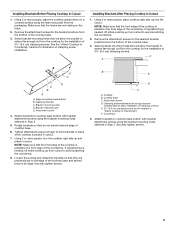
... more people, place the cooktop upside down on the foam. 2. Bracket mounting holes D. Attachment screw 4. Cooktop base C. Attach brackets to be installed in cutout. 7. Installing Brackets After Placing Cooktop in Step 3. Edge of the countertop. B E D C A. Clamping bracket (extends far enough beyond its edge. ... screws) E. 2½" (6.4 cm) clamping screw (to cooktop base bottom with bracket attachment screws using the foam end posts from cutout to extend far enough out from the bottom of the cooktop base. 3. Rotate brackets so they are not resting on a covered ...
... more people, place the cooktop upside down on the foam. 2. Bracket mounting holes D. Attachment screw 4. Cooktop base C. Attach brackets to be installed in cutout. 7. Installing Brackets After Placing Cooktop in Step 3. Edge of the countertop. B E D C A. Clamping bracket (extends far enough beyond its edge. ... screws) E. 2½" (6.4 cm) clamping screw (to cooktop base bottom with bracket attachment screws using the foam end posts from cutout to extend far enough out from the bottom of the cooktop base. 3. Rotate brackets so they are not resting on a covered ...
Dimension Guide
Page 1
...of the countertop to the top of electrical connection you must determine the type of the drawer (or other obstruction) in the future. Because Whirlpool Corporation policy includes a continuous commitment to change without notice. W10346695A 7/26/12 q A 3-wire or 4-wire, single phase, 120/240...right side combustible surface above ) C. 30" (76.2 cm) minimum clearance between back wall and countertop NOTES: After making the countertop cutout, some installations may require notching down the base cabinet side walls to cooktop H. For complete details, see Installation our products, we ...
...of the countertop to the top of electrical connection you must determine the type of the drawer (or other obstruction) in the future. Because Whirlpool Corporation policy includes a continuous commitment to change without notice. W10346695A 7/26/12 q A 3-wire or 4-wire, single phase, 120/240...right side combustible surface above ) C. 30" (76.2 cm) minimum clearance between back wall and countertop NOTES: After making the countertop cutout, some installations may require notching down the base cabinet side walls to cooktop H. For complete details, see Installation our products, we ...