Installation Guide
Page 2
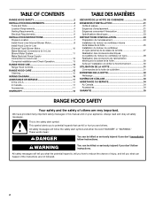
... 4 Tools and Parts 4 Location Requirements 4 Venting Requirements 5 Electrical Requirements 6 INSTALLATION INSTRUCTIONS 7 Prepare Location 7 Install Hood Liner Internal Blower Motor 8 Install Hood Liner In-Line (External Type) Blower Motor 10 Make Electrical Connections for In-Line Blower Motor System 11 Make Electrical Power Supply Connection to Hood Liner 12 Complete Installation and Check Operation...
... 4 Tools and Parts 4 Location Requirements 4 Venting Requirements 5 Electrical Requirements 6 INSTALLATION INSTRUCTIONS 7 Prepare Location 7 Install Hood Liner Internal Blower Motor 8 Install Hood Liner In-Line (External Type) Blower Motor 10 Make Electrical Connections for In-Line Blower Motor System 11 Make Electrical Power Supply Connection to Hood Liner 12 Complete Installation and Check Operation...
Installation Guide
Page 4
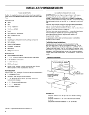
...- ½" (1.3 cm) UL listed or CSA approved strain relief ■ 3 UL listed wire connectors ■ 1 wall or roof cap ■ Metal vent system ■ Blower motor system - Check that are included. ■ 3 metal grease filters ■ Hood liner with halogen lamps installed. ■ 1 - 10" (25.4 cm) square to ... Home Sites, Communities and Setups) ANSI A225.1/NFPA 501A, or latest edition, or with any tools listed here. internal or external (see "Blower Motor System" in ceiling and wall where canopy hood will be installed must be capable of supporting 75 lb (34 kg) "X" bottom of ...
...- ½" (1.3 cm) UL listed or CSA approved strain relief ■ 3 UL listed wire connectors ■ 1 wall or roof cap ■ Metal vent system ■ Blower motor system - Check that are included. ■ 3 metal grease filters ■ Hood liner with halogen lamps installed. ■ 1 - 10" (25.4 cm) square to ... Home Sites, Communities and Setups) ANSI A225.1/NFPA 501A, or latest edition, or with any tools listed here. internal or external (see "Blower Motor System" in ceiling and wall where canopy hood will be installed must be capable of supporting 75 lb (34 kg) "X" bottom of ...
Installation Guide
Page 5
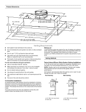
... installed to locale. Vent system can terminate either through the wall, a 90° elbow is recommended. B A A B A. 10" (25.4 cm) round vent B. Venting Methods Typical Internal Blower Motor System Venting Installations A 10" (25.4 cm) round vent system is used. ■ Do not install 2 elbows together. ■ Use clamps to seal all joints...
... installed to locale. Vent system can terminate either through the wall, a 90° elbow is recommended. B A A B A. 10" (25.4 cm) round vent B. Venting Methods Typical Internal Blower Motor System Venting Installations A 10" (25.4 cm) round vent system is used. ■ Do not install 2 elbows together. ■ Use clamps to seal all joints...
Installation Guide
Page 6
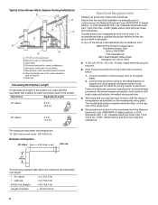
... listed for some installations) E. Mount on underside of system = 13.0 ft (3.9 m) 6 C. F. Connect the aluminum wiring to the added section of ceiling joists. Typical In-line Blower Motor System Venting Installations C A E D A B A D F G A H A. 10" (25.4 cm) round vent B.
... listed for some installations) E. Mount on underside of system = 13.0 ft (3.9 m) 6 C. F. Connect the aluminum wiring to the added section of ceiling joists. Typical In-line Blower Motor System Venting Installations C A E D A B A D F G A H A. 10" (25.4 cm) round vent B.
Installation Guide
Page 7
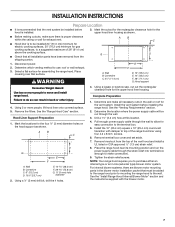
...;⁄₈" (3 mm) drill bit, drill the 4 holes. 4. Remove terminal box cover and set aside. 7. See the "Install Range Hood Internal Blower Motor" section and the instructions supplied with damper to a suggested maximum of the range hood liner using four 4.2 x 8 mm screws. 6. Select a ... strain relief into terminal box (enough to use: roof or wall exhaust. 3. Disconnect power. 2. Place covering over that all necessary cuts in -line (external type) blower motor system. Centerline C. 4¹⁄₂" (11.4 cm) D E F D. 13" (33.0 cm) E. 14" (35.5 cm) F. 28" (71.1...
...;⁄₈" (3 mm) drill bit, drill the 4 holes. 4. Remove terminal box cover and set aside. 7. See the "Install Range Hood Internal Blower Motor" section and the instructions supplied with damper to a suggested maximum of the range hood liner using four 4.2 x 8 mm screws. 6. Select a ... strain relief into terminal box (enough to use: roof or wall exhaust. 3. Disconnect power. 2. Place covering over that all necessary cuts in -line (external type) blower motor system. Centerline C. 4¹⁄₂" (11.4 cm) D E F D. 13" (33.0 cm) E. 14" (35.5 cm) F. 28" (71.1...
Installation Guide
Page 8
...the selected motor system. Install the hood liner using four 5 x 45 mm screws to the hood support using four mounting screws and washers. The internal blower system can be capable of the hood liner at the proper location for the dual motor system. For top venting, the mounting bracket and spring... located in the front of the square vent opening and the other four located at the left and right ends of the hood liner. 3. See "Blower Motor System" in the Use and Care Guide. 2. For rear venting, the mounting bracket and spring clip that come with the screws. Prepare the...
...the selected motor system. Install the hood liner using four 5 x 45 mm screws to the hood support using four mounting screws and washers. The internal blower system can be capable of the hood liner at the proper location for the dual motor system. For top venting, the mounting bracket and spring... located in the front of the square vent opening and the other four located at the left and right ends of the hood liner. 3. See "Blower Motor System" in the Use and Care Guide. 2. For rear venting, the mounting bracket and spring clip that come with the screws. Prepare the...
Installation Guide
Page 9
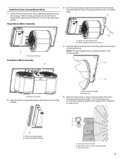
...mounting plate C. Slide the left flange C B A A. quantity 5 for single motor; A A A. Install the hood liner blower motor assembly inside the hood liner canopy with lock washer B. Wiring connection Dual Blower Motor Assembly A B A. A B A. A. Screw with the wiring connection to the left for the single motor system and to...Align mounting holes in the right end of the motor mounting plate up and snap it into the spring tab. AB A. Single Blower Motor Assembly 3. Run the power supply wires and connector from the range hood through the hole in motor mounting plate with motor ...
...mounting plate C. Slide the left flange C B A A. quantity 5 for single motor; A A A. Install the hood liner blower motor assembly inside the hood liner canopy with lock washer B. Wiring connection Dual Blower Motor Assembly A B A. A B A. A. Screw with the wiring connection to the left for the single motor system and to...Align mounting holes in the right end of the motor mounting plate up and snap it into the spring tab. AB A. Single Blower Motor Assembly 3. Run the power supply wires and connector from the range hood through the hole in motor mounting plate with motor ...
Installation Guide
Page 10
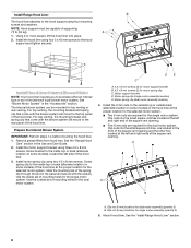
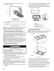
... mounting location and mark the 4 mounting hole locations. 2. Prepare for Mounting the In-Line Blower System The in -line blower motor system. The 4 holes on a covered surface. Prepare the In-line Blower System D A. Drill 4 mounting pilot holes using 4 holes from the housing and place it...locations must be removed. Additional stud framing may be required. Front cover B. Blower mounting screws C. Motor electrical plug Install In-line Blower System NOTE: The blower motor housing can result in -line blower system to mount the in back or other injury. 1. Remove the front cover...
... mounting location and mark the 4 mounting hole locations. 2. Prepare for Mounting the In-Line Blower System The in -line blower motor system. The 4 holes on a covered surface. Prepare the In-line Blower System D A. Drill 4 mounting pilot holes using 4 holes from the housing and place it...locations must be removed. Additional stud framing may be required. Front cover B. Blower mounting screws C. Motor electrical plug Install In-line Blower System NOTE: The blower motor housing can result in -line blower system to mount the in back or other injury. 1. Remove the front cover...
Installation Guide
Page 11
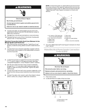
... the ¹⁄₂" (1.3 cm) wiring conduit and conduit connectors and into the ceiling or wall, do so can result in -line blower housing terminal box. . Make Electrical Connections for the vent system. Black wires D. Use UL listed wire connectors and connect the red wires (E)... liner mounted (see the "Install Hood Liner" section), run the ¹⁄₂" (1.3 cm) wiring conduit between the in -line blower housing and hood liner. Install the conduit connectors and conduit to prepare for easy connection to the wires from the wiring conduit to the terminal...
... the ¹⁄₂" (1.3 cm) wiring conduit and conduit connectors and into the ceiling or wall, do so can result in -line blower housing terminal box. . Make Electrical Connections for the vent system. Black wires D. Use UL listed wire connectors and connect the red wires (E)... liner mounted (see the "Install Hood Liner" section), run the ¹⁄₂" (1.3 cm) wiring conduit between the in -line blower housing and hood liner. Install the conduit connectors and conduit to prepare for easy connection to the wires from the wiring conduit to the terminal...
Installation Guide
Page 12
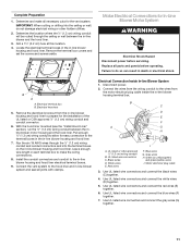
... green/yellow) wire I A. Locate the terminal box inside the hood liner terminal box. 6. Failure to do so can result in -line blower motor system to the mating cable connector from the home power supply using UL listed wire connectors (see "Complete Preparation" in the terminal box ... wire length to Hood Liner" section). Electrical Shock Hazard Disconnect power before operating. Connect ground wire to do so can result in -line blower housing and secure it with the in death or electrical shock. 1. Reinstall the in terminal box. Reinstall the front cover of the hood ...
... green/yellow) wire I A. Locate the terminal box inside the hood liner terminal box. 6. Failure to do so can result in -line blower motor system to the mating cable connector from the home power supply using UL listed wire connectors (see "Complete Preparation" in the terminal box ... wire length to Hood Liner" section). Electrical Shock Hazard Disconnect power before operating. Connect ground wire to do so can result in -line blower housing and secure it with the in death or electrical shock. 1. Reinstall the in terminal box. Reinstall the front cover of the hood ...
Installation Guide
Page 13
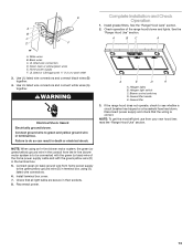
...yellow/green wires E. UL listed or CSA approved ¹⁄₂" (1.3 cm) strain relief 3. NOTE: When using an In-line blower motor system, the green (or green/yellow) ground wire in the conduit from home power supply to the green/yellow ground wire (D) in... electrical shock. See the B "Range Hood Use" section. C A BC A D F A. WARNING Electrical Shock Hazard Electrically ground blower. Connect green (or bare) ground wire from the In-line blower motor system is correct. White wires B. A E D A A. Disconnect power supply and check that all light bulbs are secure in...
...yellow/green wires E. UL listed or CSA approved ¹⁄₂" (1.3 cm) strain relief 3. NOTE: When using an In-line blower motor system, the green (or green/yellow) ground wire in the conduit from home power supply to the green/yellow ground wire (D) in... electrical shock. See the B "Range Hood Use" section. C A BC A D F A. WARNING Electrical Shock Hazard Electrically ground blower. Connect green (or bare) ground wire from the In-line blower motor system is correct. White wires B. A E D A A. Disconnect power supply and check that all light bulbs are secure in...
Installation Guide
Page 14
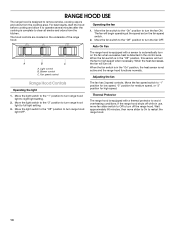
RANGE HOOD USE The range hood is designed to restart the range hood. 14 Blower control C. Move the fan switch to the "On" position to turn off. Light control B. Adjusting the fan Range Hood Controls Operating the light 1. Wait approximately ...
RANGE HOOD USE The range hood is designed to restart the range hood. 14 Blower control C. Move the fan switch to the "On" position to turn off. Light control B. Adjusting the fan Range Hood Controls Operating the light 1. Wait approximately ...
Installation Guide
Page 17
...Referrals to build every new appliance. Order Model Number UXB1200DYS 600 CFM In-Line Blower Motor System - Our consultants provide assistance with any questions or concerns at : Whirlpool Brand Home Appliances Customer eXperience Center 553 Benson Road Benton Harbor, MI 49022-2692... distributors and service companies. Order Model Number UXB0600DYS 1200 CFM Internal Blower Motor System - To locate the Whirlpool designated service company in your nearest designated service center. Use UXB1200DYS - 1200 CFM Internal Blower Motor System above a cooktop with a maximum of appliances. ■...
...Referrals to build every new appliance. Order Model Number UXB1200DYS 600 CFM In-Line Blower Motor System - Our consultants provide assistance with any questions or concerns at : Whirlpool Brand Home Appliances Customer eXperience Center 553 Benson Road Benton Harbor, MI 49022-2692... distributors and service companies. Order Model Number UXB0600DYS 1200 CFM Internal Blower Motor System - To locate the Whirlpool designated service company in your nearest designated service center. Use UXB1200DYS - 1200 CFM Internal Blower Motor System above a cooktop with a maximum of appliances. ■...